In this lesson, I’ll explain how to configure MPLS VPN per VRF TE tunnels. If you haven’t configured MPLS VPN over TE tunnels before, look at our MPLS VPN over MPLS TE tunnels first.
Building a TE tunnel for customer VRFs doesn’t make much sense because of scalability issues. If you have more traffic in a VRF than a single TE tunnel can support, you have an issue. It could make sense when you use VRFs for central services that require strict QoS requirements.
Having said that, let’s dive into the configuration.
Configuration
To make this work, we need to configure three items for each VRF that require its own TE tunnel:
- A new loopback interface with an IP address that we’ll use as the BGP next hop.
- Change the VRF so it uses the BGP next hop of the loopback interface.
- A static route for each BGP next hop that points to the TE tunnel.
Here is the topology we’ll use:
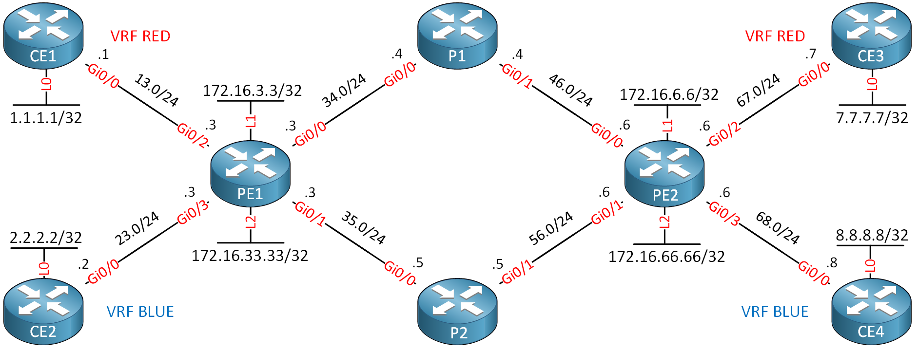
Here’s what we have:
- CE1 and CE3 are in VRF RED.
- CE2 and CE4 are in VRF BLUE.
- The CE routers have a loopback interface which we’ll use to verify reachability.
- PE1, P1, P2, and PE2 run MPLS TE.
- We have two unidirectional TE tunnels from PE1 to PE2 and PE2 to PE1:
- These tunnels both use the loopback0 interfaces on PE1 and PE2 (not shown in the picture).
- Tunnel two has an explicit path so that it uses the path through P2.
We’ll configure this network so that VRF RED uses tunnel one and VRF BLUE uses tunnel two.
I use Cisco IOS Software, IOSv Software (VIOS-ADVENTERPRISEK9-M), Version 15.9(3)M6, RELEASE SOFTWARE (fc1) on all routers.
Technically, you don’t need MPLS LDP on this network because we use TE tunnels from PE1 to PE2 and vice versa. RSVP supplies the required labels.
- Configurations
- CE1
- CE2
- CE3
- CE4
- P1
- P2
- PE1
- PE2
Want to take a look for yourself? Here, you will find the startup configuration of each device.
Loopback Interfaces
We’ll start with the loopback interfaces. We need one for each VRF:
PE1(config)#interface Loopback1
PE1(config-if)#ip address 172.16.3.3 255.255.255.255

PE1(config-if)#interface Loopback2
PE1(config-if)#ip address 172.16.33.33 255.255.255.255PE2(config)#interface Loopback1
PE2(config-if)#ip address 172.16.6.6 255.255.255.255
PE2(config-if)#interface Loopback2
PE2(config-if)#ip address 172.16.66.66 255.255.255.255BGP Next-Hop
Under the VRF configuration, we use the bgp next-hop command to change the BGP next hop:
PE1 & PE2
(config)#ip vrf RED
(config-vrf)#bgp next-hop Loopback1

(config)#ip vrf BLUE
(config-vrf)#bgp next-hop Loopback2
Static Routes
The only thing left to do is configure a static route so that we reach the BGP next hops through the TE tunnels:
PE1(config)#ip route 172.16.6.6 255.255.255.255 Tunnel1
PE1(config)#ip route 172.16.66.66 255.255.255.255 Tunnel2PE2(config)#ip route 172.16.3.3 255.255.255.255 Tunnel1
PE2(config)#ip route 172.16.33.33 255.255.255.255 Tunnel2This completes the configuration.
Verification
Let’s verify our work. I’ll use PE1 to show you everything we need to know. First, we’ll make sure that tunnels are up and running:
PE1#show mpls traffic-eng tunnels tunnel 1

Name: PE1_t1                              (Tunnel1) Destination: 6.6.6.6
  Status:
    Admin: up         Oper: up     Path: valid       Signalling: connected
    path option 1, type dynamic (Basis for Setup, path weight 20)

  Config Parameters:
    Bandwidth: 750      kbps (Global)  Priority: 7  7   Affinity: 0x0/0xFFFF
    Metric Type: TE (default)
    AutoRoute:  disabled  LockDown: disabled  Loadshare: 750      bw-based
    auto-bw: disabled
  Active Path Option Parameters:
    State: dynamic path option 1 is active
    BandwidthOverride: disabled  LockDown: disabled  Verbatim: disabled


  InLabel  :  -
  OutLabel : GigabitEthernet0/0, 21
  RSVP Signalling Info:
       Src 3.3.3.3, Dst 6.6.6.6, Tun_Id 1, Tun_Instance 44
    RSVP Path Info:
      My Address: 192.168.34.3
      Explicit Route: 192.168.34.4 192.168.46.4 192.168.46.6 6.6.6.6
      Record   Route:   NONE
      Tspec: ave rate=750 kbits, burst=1000 bytes, peak rate=750 kbits
    RSVP Resv Info:
      Record   Route:   NONE
      Fspec: ave rate=750 kbits, burst=1000 bytes, peak rate=750 kbits
  Shortest Unconstrained Path Info:
    Path Weight: 20 (TE)
    Explicit Route: 192.168.34.3 192.168.34.4 192.168.46.4 192.168.46.6
                    6.6.6.6
  History:
    Tunnel:
      Time since created: 15 hours, 29 minutes
      Time since path change: 15 hours, 9 minutes
      Number of LSP IDs (Tun_Instances) used: 44
    Current LSP:
      Uptime: 15 hours, 9 minutes
Tunnel one is connected and uses the path through P1. We use label 21. Let’s check tunnel two:
PE1#show mpls traffic-eng tunnels tunnel 2

Name: PE1_t2                              (Tunnel2) Destination: 6.6.6.6
  Status:
    Admin: up         Oper: up     Path: valid       Signalling: connected
    path option 1, type explicit INCLUDE_P2 (Basis for Setup, path weight 10)

  Config Parameters:
    Bandwidth: 750      kbps (Global)  Priority: 7  7   Affinity: 0x0/0xFFFF
    Metric Type: TE (default)
    AutoRoute:  disabled  LockDown: disabled  Loadshare: 750      bw-based
    auto-bw: disabled
  Active Path Option Parameters:
    State: explicit path option 1 is active
    BandwidthOverride: disabled  LockDown: disabled  Verbatim: disabled


  InLabel  :  -
  OutLabel : GigabitEthernet0/1, 21
  RSVP Signalling Info:
       Src 3.3.3.3, Dst 6.6.6.6, Tun_Id 2, Tun_Instance 46
    RSVP Path Info:
      My Address: 192.168.35.3
      Explicit Route: 192.168.35.5 5.5.5.5
      Record   Route:   NONE
      Tspec: ave rate=750 kbits, burst=1000 bytes, peak rate=750 kbits
    RSVP Resv Info:
      Record   Route:   NONE
      Fspec: ave rate=750 kbits, burst=1000 bytes, peak rate=750 kbits
  Shortest Unconstrained Path Info:
    Path Weight: 20 (TE)
    Explicit Route: 192.168.34.3 192.168.34.4 192.168.46.4 192.168.46.6
                    6.6.6.6
  History:
    Tunnel:
      Time since created: 15 hours, 30 minutes
      Time since path change: 14 hours, 58 minutes
      Number of LSP IDs (Tun_Instances) used: 46
    Current LSP:
      Uptime: 14 hours, 48 minutes
      Selection: reoptimization
    Prior LSP:
      ID: path option 1 [44]
      Removal Trigger: reoptimization completed
Tunnel two is also connected and uses the path through P2. We use label 21 for this tunnel.
Let’s check MP-BGP:
PE1#show ip bgp vpnv4 all
BGP table version is 9, local router ID is 172.16.33.33
Status codes: s suppressed, d damped, h history, * valid, > best, i - internal,
              r RIB-failure, S Stale, m multipath, b backup-path, f RT-Filter,
              x best-external, a additional-path, c RIB-compressed,
              t secondary path,
Origin codes: i - IGP, e - EGP, ? - incomplete
RPKI validation codes: V valid, I invalid, N Not found

     Network          Next Hop            Metric LocPrf Weight Path
Route Distinguisher: 1:1 (default for vrf RED)
 *>   1.1.1.1/32       192.168.13.1             2         32768 ?
 *>i  7.7.7.7/32       172.16.6.6               2    100      0 ?
 *>   192.168.13.0     0.0.0.0                  0         32768 ?
 *>i  192.168.67.0     172.16.6.6               0    100      0 ?
Route Distinguisher: 2:2 (default for vrf BLUE)
 *>   2.2.2.2/32       192.168.23.2             2         32768 ?
 *>i  8.8.8.8/32       172.16.66.66             2    100      0 ?
 *>   192.168.23.0     0.0.0.0                  0         32768 ?
 *>i  192.168.68.0     172.16.66.66             0    100      0 ?
Above, we see the two VRFs and the routes PE1 learned. You can see that we use different BGP next hops. For example:
- 7.7.7.7/32 (CE3) uses next hop 172.16.6.6 (loopback 1 of PE2)
- 8.8.8.8/32 (CE4) uses next hop 172.16.66.66 (loopback 2 of PE2)
You can also look at one particular entry which also tells us the label we use for this route:
- Unit 1: Introduction
- Unit 2: LDP (Label Distribution Protocol)
- Unit 3: MPLS VPN
- VRFs (Virtual Routing and Forwarding)
- MPLS L3 VPN Explained
- MPLS L3 VPN Configuration
- MPLS L3 VPN BGP Allow AS in
- MPLS L3 VPN BGP AS Override
- MPLS L3 VPN PE-CE RIP
- MPLS L3 VPN PE-CE EIGRP
- MPLS L3 VPN PE-CE OSPF
- MPLS L3 VPN PE-CE OSPF Default Route
- MPLS L3 VPN PE-CE OSPF Global Default Route
- MPLS L3 VPN PE-CE OSPF Sham Link
- VRF Lite Route Leaking
- MPLS VPN Extranet Route Leaking
- MPLS VPN VRF Export Map
- MPLS VPN VRF Import Map
- MPLS over FlexVPN
- Unit 4: MPLS L2 Encapsulation
- Unit 5: IPv6 MPLS
- Unit 6: MPLS Traffic Engineering (TE)
- Introduction to MPLS Traffic Engineering (TE)
- MPLS Traffic Engineering (TE) IS-IS Configuration
- MPLS Traffic Engineering (TE) OSPF Configuration
- MPLS TE RSVP-TE
- MPLS TE Static Routes
- MPLS TE Policy Based Routing (PBR)
- MPLS TE Autoroute Announce
- MPLS TE Autoroute Destination
- MPLS TE Autoroute Metric
- MPLS TE Unequal Cost Load Balancing
- MPLS TE Load Balancing between IGP and TE
- MPLS TE Forwarding Adjacency
- MPLS TE Path Options Explicit
- MPLS TE Class-Based Tunnel Selection (CBTS)
- MPLS TE Metric
- MPLS TE Setup and Hold Priority
- MPLS TE Attribute Flag and Affinity
- MPLS TE Reoptimization
- MPLS TE Fast Reroute (FRR)
- MPLS TE Fast Reroute Path Link Protection
- MPLS TE Fast Reroute Path Node Protection
- MPLS TE FRR RSVP Hello Support
- MPLS TE DiffServ Aware (DS-TE) Traditional
- MPLS TE Diffserv-Aware (DS-TE) IETF Mode
- MPLS VPN over MPLS TE Tunnels
- MPLS TE Per VRF TE tunnel