In an MPLS VPN PE-CE network, some customers might require Internet access. One way to achieve this is by routing your traffic from the VRF to the global routing table and back. Another way to provide Internet access is to advertise a default route within a VRF, as we did in the MPLS VPN PE-CE OSPF default route lesson.
I’ll explain how to “leak” traffic from a VRF to the global routing table in this lesson. We’ll configure necessary static routes in the VRF and global routing table and advertise required routes through OSPF.
Let’s get started!
Configuration
Here is the topology we’ll use:
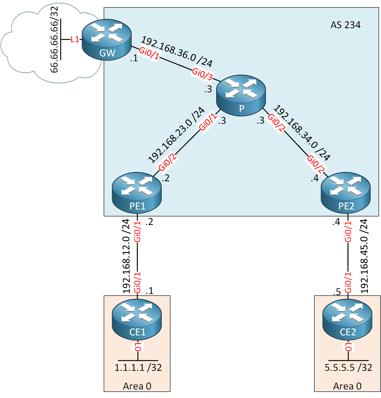
The topology is the same as the one I use in the MPLS VPN PE-CE OSPF lesson but I added a GW router that is connected to the “Internet”. The 66.66.66.66/32 address on the GW router simulates a server on the Internet.
- Configurations
- CE1
- CE2
- GW
- P
- PE1
- PE2
Want to take a look for yourself? Here you will find the startup configuration of each device.
OSPF between P and GW
First, we’ll configure OSPF on the GW and P routers. I advertise a loopback interface on the GW router which we need later as the next-hop address for a static route:
GW(config)#router ospf 1
GW(config-router)#network 6.6.6.6 0.0.0.0 area 0
GW(config-router)#network 192.168.36.0 0.0.0.255 area 0P(config)#router ospf 1
P(config-router)#network 192.168.36.0 0.0.0.255 area 0From VRF to Global
Let’s focus on getting traffic from the VRF to the global routing table. We can do this by configuring a static route on the PE routers and adding the global parameter. This tells the router that the next hop is in the global routing table, not in the VRF:
PE1 & PE2
(config)#ip route vrf CUSTOMER 0.0.0.0 0.0.0.0 6.6.6.6 global
The static route is now on the PE routers but we also need it on the CE routers. Let’s configure OSPF to advertise a default route in the VRF:
PE1 & PE2
(config)#router ospf 2 vrf CUSTOMER
(config-router)#default-information originate
OSPF will only advertise a default route when the PE routers have a default route in their routing tables. Thanks to this default route, the CE routers now know to reach unknown destinations.
The static default route on PE1 and PE2 will always be in the global routing table as long as 6.6.6.6 is reachable, even when there is no Internet access. This also means the CE routers receive the default route through OSPF. It’s not a bad idea to combine the static default route with IP SLA to ensure that it will be withdrawn when there is no Internet connectivity. Otherwise, you might forward traffic that is dropped by the GW router.
From Global to VRF
Our CE routers can make it to the GW router, but we also have to think about the return traffic. The GW router somehow needs to know how it can reach 1.1.1.1 (CE1) or 5.5.5.5 (CE2). The traffic is routed in the global routing table, so we need something there.
To achieve this, I will add a static route in the global routing table on the PE routers which points to the CE routers. I will redistribute these static routes into OSPF so that the GW and P routers know how to reach these networks.
If you use public IP addresses in your VRFs, you’ll need BGP so that you can advertise these prefixes to other ASes. I’m using OSPF because our P router is not configured for BGP.
PE1
The static route that points to the VRF must point to an interface and if it’s a multi-access interface, we also have to include the next-hop IP address. This static route is in the global routing table but the next-hop IP address is in the VRF. Normally, this static route would be invalid but with MPLS VPN, this is a valid configuration. Here’s the static route:
- Unit 1: Introduction
- Unit 2: LDP (Label Distribution Protocol)
- Unit 3: MPLS VPN
- VRFs (Virtual Routing and Forwarding)
- MPLS L3 VPN Explained
- MPLS L3 VPN Configuration
- MPLS L3 VPN BGP Allow AS in
- MPLS L3 VPN BGP AS Override
- MPLS L3 VPN PE-CE RIP
- MPLS L3 VPN PE-CE EIGRP
- MPLS L3 VPN PE-CE OSPF
- MPLS L3 VPN PE-CE OSPF Default Route
- MPLS L3 VPN PE-CE OSPF Global Default Route
- MPLS L3 VPN PE-CE OSPF Sham Link
- VRF Lite Route Leaking
- MPLS VPN Extranet Route Leaking
- MPLS VPN VRF Export Map
- MPLS VPN VRF Import Map
- MPLS over FlexVPN
- Unit 4: MPLS L2 Encapsulation
- Unit 5: IPv6 MPLS
- Unit 6: MPLS Traffic Engineering (TE)
- Introduction to MPLS Traffic Engineering (TE)
- MPLS Traffic Engineering (TE) IS-IS Configuration
- MPLS Traffic Engineering (TE) OSPF Configuration
- MPLS TE RSVP-TE
- MPLS TE Static Routes
- MPLS TE Policy Based Routing (PBR)
- MPLS TE Autoroute Announce
- MPLS TE Autoroute Destination
- MPLS TE Autoroute Metric
- MPLS TE Unequal Cost Load Balancing
- MPLS TE Load Balancing between IGP and TE
- MPLS TE Forwarding Adjacency
- MPLS TE Path Options Explicit
- MPLS TE Class-Based Tunnel Selection (CBTS)
- MPLS TE Metric
- MPLS TE Setup and Hold Priority
- MPLS TE Attribute Flag and Affinity
- MPLS TE Reoptimization
- MPLS TE Fast Reroute (FRR)
- MPLS TE Fast Reroute Path Link Protection
- MPLS TE Fast Reroute Path Node Protection
- MPLS TE FRR RSVP Hello Support
- MPLS TE DiffServ Aware (DS-TE) Traditional
- MPLS TE Diffserv-Aware (DS-TE) IETF Mode
- MPLS VPN over MPLS TE Tunnels
- MPLS TE Per VRF TE tunnel