In the MPLS Traffic Engineering (TE) IS-IS Configuration lesson and other MPLS TE lessons, I use IS-IS as the IGP on the TE routers. In this lesson, we’ll use OSPF instead.
I’ll walk you through the entire configuration, but because I already explained in detail how to configure an MPLS TE network step-by-step, I’ll only focus on OSPF here. This is the topology we’ll use:
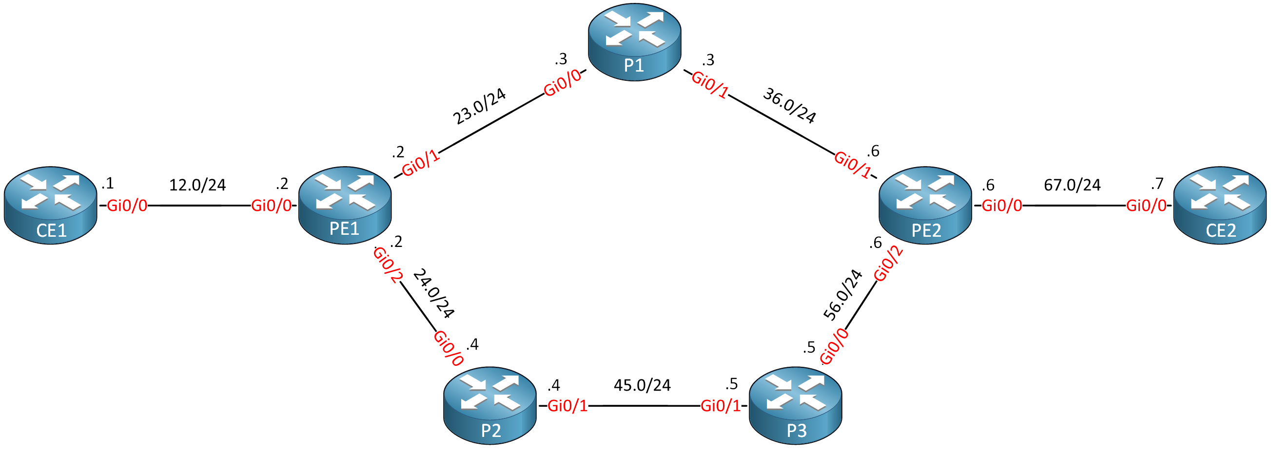
Routers PE1, P1, P2, P3, and PE2 are our MPLS core network. The CE1 and CE2 routers use regular IP routing. All routers are configured to use OSPF area 0 and MPLS is enabled on the interfaces. I use Cisco IOS Software, IOSv Software (VIOS-ADVENTERPRISEK9-M), Version 15.9(3)M4.
- Configurations
- CE1
- CE2
- P1
- P2
- P3
- PE1
- PE2
Want to take a look for yourself? Here, you will find the startup configuration of each device.
Before we continue, let’s make sure we have a label-switched path (LSP) when we send traffic from CE1 to CE2:
CE1#traceroute 7.7.7.7 source 1.1.1.1 probe 1
Type escape sequence to abort.
Tracing the route to 7.7.7.7
VRF info: (vrf in name/id, vrf out name/id)
  1 192.168.12.2 1 msec
  2 192.168.23.3 [MPLS: Label 23 Exp 0] 4 msec
  3 192.168.36.6 [MPLS: Label 19 Exp 0] 3 msec
  4 192.168.67.7 4 msec
The LSP is working.
Configuration
Let’s configure this “regular” MPLS network into a network that supports MPLS TE. There are four main items we have to configure:
- Enable MPLS TE support:
- Globally
- Interfaces
- Configure OSPF to support MPLS TE.
- Configure RSVP.
- Configure a TE tunnel interface.
We configure these items on all MPLS routers where you want to use MPLS TE. Let’s get started.
Global
The global mpls traffic-eng tunnels command enables MPLS TE globally:
PE1, P1, P2, P3, and PE2
(config)#mpls traffic-eng tunnels
Interfaces
We have to enable MPLS TE support on all interfaces that connect the PE and P routers:
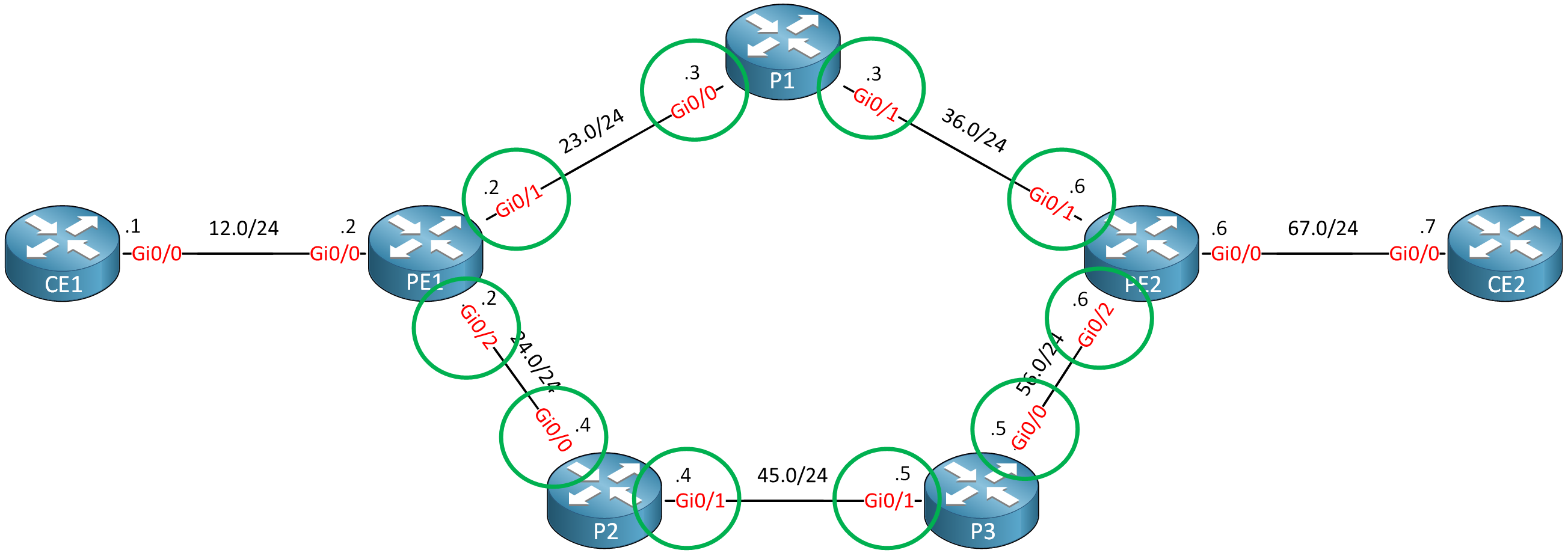
This is the configuration:
PE1 and PE2
(config)#interface range GigabitEthernet 0/1 - 2
(config-if-range)#mpls traffic-eng tunnels
P1, P2, and P3
(config)#interface range GigabitEthernet 0/0 - 1
(config-if-range)#mpls traffic-eng tunnelsThat’s all you need.
OSPF
There are two things we need to configure for OSPF to support MPLS TE:
- Enable MPLS TE for the area.
- Configure the router ID.
Here’s how to do it:
PE1, PE2, P1, P2 & P3
(config)#router ospf 1
(config-router)#mpls traffic-eng area 0
(config-router)#mpls traffic-eng router-id loopback 0
RSVP
Let’s configure RSVP to use up to the interface bandwidth:
PE1 and PE2
(config)#interface range GigabitEthernet 0/1 - 2
(config-if-range)#ip rsvp bandwidth 1000000
P1, P2, and P3
(config)#interface range GigabitEthernet 0/0 - 1
(config-if-range)#ip rsvp bandwidth 1000000Tunnel Interface
Let’s configure a tunnel interface between PE1 and PE2:
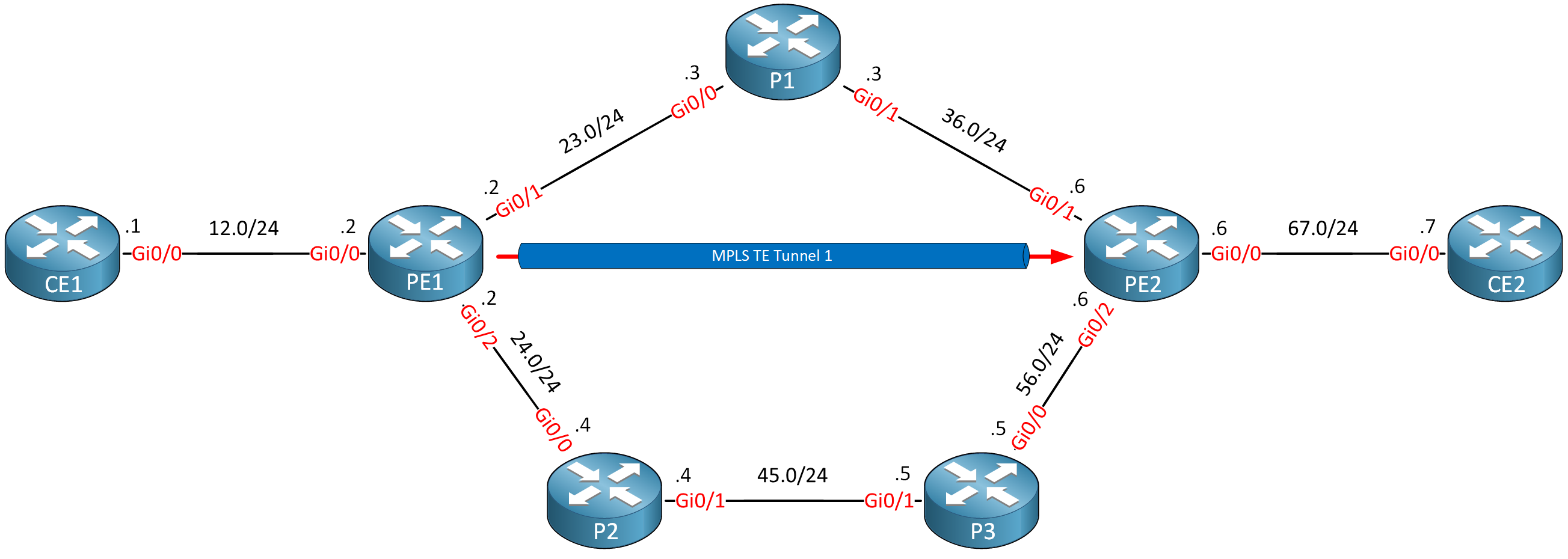
This is how you configure a tunnel interface:
PE1(config)#interface Tunnel 1
PE1(config-if)#ip unnumbered Loopback 0
PE1(config-if)#tunnel mode mpls traffic-eng
PE1(config-if)#tunnel destination 6.6.6.6
PE1(config-if)#tunnel mpls traffic-eng bandwidth 750
PE1(config-if)#tunnel mpls traffic-eng path-option 1 dynamic- Unit 1: Introduction
- Unit 2: LDP (Label Distribution Protocol)
- Unit 3: MPLS VPN
- VRFs (Virtual Routing and Forwarding)
- MPLS L3 VPN Explained
- MPLS L3 VPN Configuration
- MPLS L3 VPN BGP Allow AS in
- MPLS L3 VPN BGP AS Override
- MPLS L3 VPN PE-CE RIP
- MPLS L3 VPN PE-CE EIGRP
- MPLS L3 VPN PE-CE OSPF
- MPLS L3 VPN PE-CE OSPF Default Route
- MPLS L3 VPN PE-CE OSPF Global Default Route
- MPLS L3 VPN PE-CE OSPF Sham Link
- VRF Lite Route Leaking
- MPLS VPN Extranet Route Leaking
- MPLS VPN VRF Export Map
- MPLS VPN VRF Import Map
- MPLS over FlexVPN
- Unit 4: MPLS L2 Encapsulation
- Unit 5: IPv6 MPLS
- Unit 6: MPLS Traffic Engineering (TE)
- Introduction to MPLS Traffic Engineering (TE)
- MPLS Traffic Engineering (TE) IS-IS Configuration
- MPLS Traffic Engineering (TE) OSPF Configuration
- MPLS TE RSVP-TE
- MPLS TE Static Routes
- MPLS TE Policy Based Routing (PBR)
- MPLS TE Autoroute Announce
- MPLS TE Autoroute Destination
- MPLS TE Autoroute Metric
- MPLS TE Unequal Cost Load Balancing
- MPLS TE Load Balancing between IGP and TE
- MPLS TE Forwarding Adjacency
- MPLS TE Path Options Explicit
- MPLS TE Class-Based Tunnel Selection (CBTS)
- MPLS TE Metric
- MPLS TE Setup and Hold Priority
- MPLS TE Attribute Flag and Affinity
- MPLS TE Reoptimization
- MPLS TE Fast Reroute (FRR)
- MPLS TE Fast Reroute Path Link Protection
- MPLS TE Fast Reroute Path Node Protection
- MPLS TE FRR RSVP Hello Support
- MPLS TE DiffServ Aware (DS-TE) Traditional
- MPLS TE Diffserv-Aware (DS-TE) IETF Mode
- MPLS VPN over MPLS TE Tunnels
- MPLS TE Per VRF TE tunnel