MPLS supports intranet and extranet VPNs:
- MPLS Intranet VPN: this is a VPN where we connect the headquarters, remote sites, branch offices, etc. from a single company.
- MPLS Extranet VPN: this is a VPN where we extend connectivity from a company to other parties like customers, suppliers, or partners.
Let me show you a quick example to explain this:
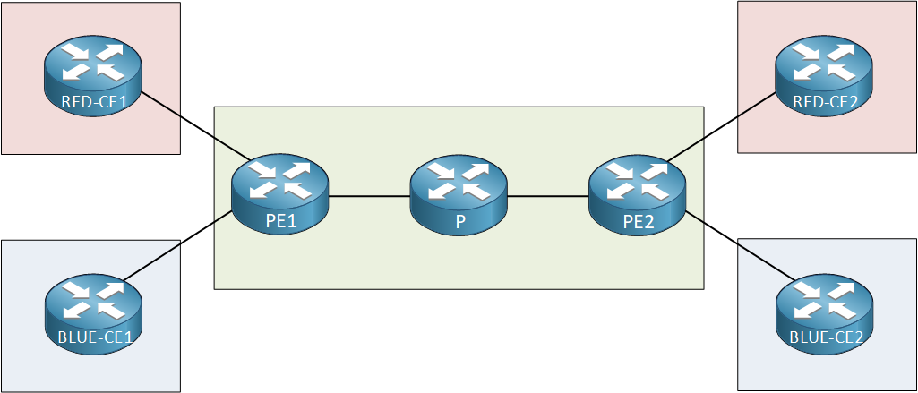
In the topology above, we have a simple MPLS VPN PE-CE topology from a provider that has two customers:
- Customer Red
- Customer Blue
Each customer has two sites. On our PE routers, we use the following configuration for our VRFs:
PE1#show run | begin ip vrf
ip vrf BLUE
 rd 2:2
 route-target export 2:2
 route-target import 2:2
!
ip vrf RED
 rd 1:1
 route-target export 1:1
route-target import 1:1PE2#show run | begin ip vrf
ip vrf BLUE
rd 2:2
route-target export 2:2
route-target import 2:2
!
ip vrf RED
rd 1:1
route-target export 1:1
route-target import 1:1Here’s what you see above:
- VRF RED uses route-target 1:1 to import and export its routes.
- VRF BLUE uses route-target 2:2 to import and export its routes.
With the configuration above, both customers are only able to communicate with their own sites. It’s impossible to send traffic from RED to BLUE or vice versa. This is what we call an MPLS intranet VPN.
Does this mean it’s impossible for customers RED and BLUE to communicate with each other at all?
This is no problem at all…the only thing we have to do is leak some routes from one VRF to another. This allows the different sites to learn about each others’ routes and they will be able to communicate with each other. This is called an MPLS VPN Extranet (Route Leaking).
Configuration
Let’s see how this works. To demonstrate this, I will use the topology I just showed you and we will leak some routes between customer site RED-CE1 and BLUE-CE2. Here it is:
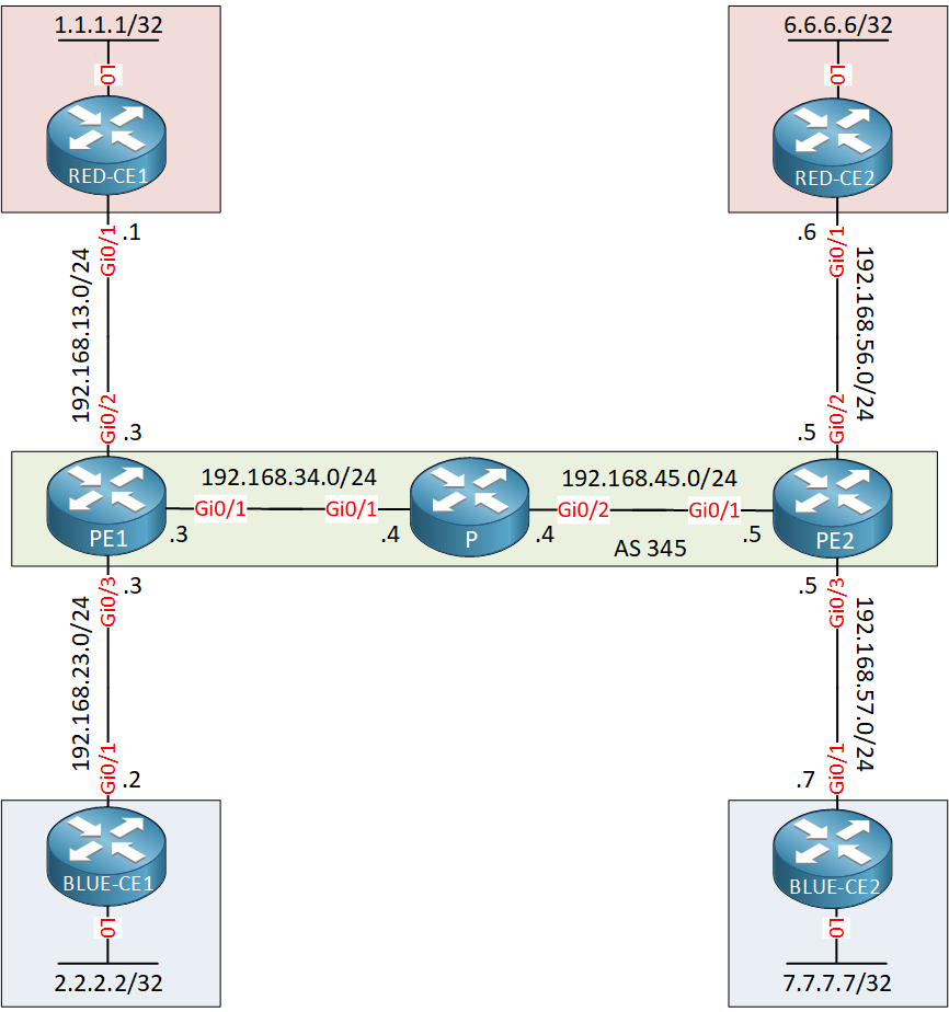
This is a basic MPLS VPN PE CE setup with two VRFs. We use OSPF as the PE-CE routing protocol.
- Configurations
- B-CE1
- B-CE2
- P
- PE1
- PE2
- R-CE1
- R-CE2
Want to take a look for yourself? Here you will find the startup configuration of each device.
Right now, we have an intranet VPN so each customer only sees their own routes. Here are customer RED’s routes:
RED-CE1#show ip route ospf

      6.0.0.0/32 is subnetted, 1 subnets
O IA     6.6.6.6 [110/3] via 192.168.13.3, 00:16:14, GigabitEthernet0/1
O IA 192.168.56.0/24 [110/2] via 192.168.13.3, 00:16:14, GigabitEthernet0/1RED-CE2#show ip route ospf
1.0.0.0/32 is subnetted, 1 subnets
O IA 1.1.1.1 [110/3] via 192.168.56.5, 00:16:37, GigabitEthernet0/1
O IA 192.168.13.0/24 [110/2] via 192.168.56.5, 00:16:37, GigabitEthernet0/1And here we have customer BLUE’s routes:
BLUE-CE1#show ip route ospf

      7.0.0.0/32 is subnetted, 1 subnets
O IA     7.7.7.7 [110/3] via 192.168.23.3, 00:16:52, GigabitEthernet0/1
O IA 192.168.57.0/24 [110/2] via 192.168.23.3, 00:16:52, GigabitEthernet0/1BLUE-CE2#show ip route ospf
2.0.0.0/32 is subnetted, 1 subnets
O IA 2.2.2.2 [110/3] via 192.168.57.5, 00:17:10, GigabitEthernet0/1
O IA 192.168.23.0/24 [110/2] via 192.168.57.5, 00:17:10, GigabitEthernet0/1If I want to let RED-CE1 and BLUE-CE2 talk with each other, I’ll have to export and import some routes. I’ll use a new route-target (1:2) for this. Let’s do this step-by-step…first, let’s export the routes from VRF RED on PE1:
- Unit 1: Introduction
- Unit 2: LDP (Label Distribution Protocol)
- Unit 3: MPLS VPN
- VRFs (Virtual Routing and Forwarding)
- MPLS L3 VPN Explained
- MPLS L3 VPN Configuration
- MPLS L3 VPN BGP Allow AS in
- MPLS L3 VPN BGP AS Override
- MPLS L3 VPN PE-CE RIP
- MPLS L3 VPN PE-CE EIGRP
- MPLS L3 VPN PE-CE OSPF
- MPLS L3 VPN PE-CE OSPF Default Route
- MPLS L3 VPN PE-CE OSPF Global Default Route
- MPLS L3 VPN PE-CE OSPF Sham Link
- VRF Lite Route Leaking
- MPLS VPN Extranet Route Leaking
- MPLS VPN VRF Export Map
- MPLS VPN VRF Import Map
- MPLS over FlexVPN
- Unit 4: MPLS L2 Encapsulation
- Unit 5: IPv6 MPLS
- Unit 6: MPLS Traffic Engineering (TE)
- Introduction to MPLS Traffic Engineering (TE)
- MPLS Traffic Engineering (TE) IS-IS Configuration
- MPLS Traffic Engineering (TE) OSPF Configuration
- MPLS TE RSVP-TE
- MPLS TE Static Routes
- MPLS TE Policy Based Routing (PBR)
- MPLS TE Autoroute Announce
- MPLS TE Autoroute Destination
- MPLS TE Autoroute Metric
- MPLS TE Unequal Cost Load Balancing
- MPLS TE Load Balancing between IGP and TE
- MPLS TE Forwarding Adjacency
- MPLS TE Path Options Explicit
- MPLS TE Class-Based Tunnel Selection (CBTS)
- MPLS TE Metric
- MPLS TE Setup and Hold Priority
- MPLS TE Attribute Flag and Affinity
- MPLS TE Reoptimization
- MPLS TE Fast Reroute (FRR)
- MPLS TE Fast Reroute Path Link Protection
- MPLS TE Fast Reroute Path Node Protection
- MPLS TE FRR RSVP Hello Support
- MPLS TE DiffServ Aware (DS-TE) Traditional
- MPLS TE Diffserv-Aware (DS-TE) IETF Mode
- MPLS VPN over MPLS TE Tunnels
- MPLS TE Per VRF TE tunnel