In this lesson we’ll take a look how we can use EIGRP as the PE-CE routing protocol for MPLS L3 VPN. If you already have seen my lesson for PE-CE RIP then you can skip to the “EIGRP between PE and CE routers” section as the configuration of the service provider network is exactly the same.
Here’s the topology we will use:
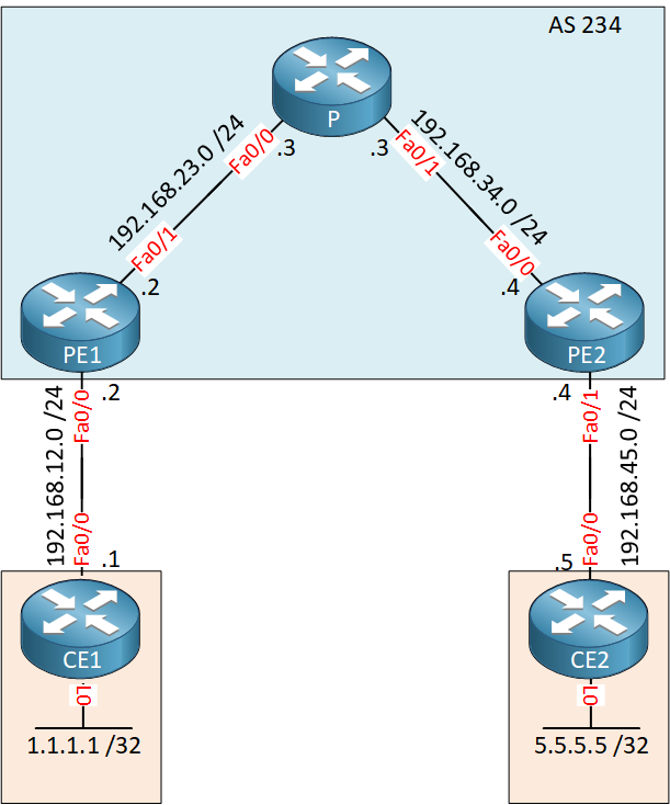
Above we have 5 routers. CE and CE2 belong to the customer who wants to run EIGRP between their sites. The service provider has two PE routers and one P router in the middle.
Configuration
IGP and LDP
Let’s prepare the service provider routers. We need an IGP (OSPF) and LDP on the PE1, PE2 and P router.
PE1(config)#interface loopback 0
PE1(config-if)#ip address 2.2.2.2 255.255.255.255P(config)#interface loopback 0
P(config-if)#ip address 3.3.3.3 255.255.255.255PE2(config)#interface loopback 0
PE2(config-if)#ip address 4.4.4.4 255.255.255.255Now we can configure OSPF:
PE1(config)#router ospf 1
PE1(config-router)#network 192.168.23.0 0.0.0.255 area 0
PE1(config-router)#network 2.2.2.2 0.0.0.0 area 0
PE1(config-router)#mpls ldp autoconfigP(config)#router ospf 1
P(config-router)#network 192.168.23.0 0.0.0.255 area 0
P(config-router)#network 192.168.34.0 0.0.0.255 area 0
P(config-router)#network 3.3.3.3 0.0.0.0 area 0
P(config-router)#mpls ldp autoconfigPE2(config)#router ospf 1
PE2(config-router)#network 192.168.34.0 0.0.0.255 area 0
PE2(config-router)#network 4.4.4.4 0.0.0.0 area 0
PE2(config-router)#mpls ldp autoconfigThis takes care of IGP and LDP. Make sure you have LDP neighbors before we continue:
P#show mpls ldp neighbor | include Peer
    Peer LDP Ident: 2.2.2.2:0; Local LDP Ident 3.3.3.3:0
    Peer LDP Ident: 4.4.4.4:0; Local LDP Ident 3.3.3.3:0
Our P router in the middle has two neighbors so this is looking good. Just in case, let’s verify if there is connectivity between PE1 and PE2:
PE1#traceroute 4.4.4.4 source loopback 0
Type escape sequence to abort.
Tracing the route to 4.4.4.4
VRF info: (vrf in name/id, vrf out name/id)
  1 192.168.23.3 [MPLS: Label 17 Exp 0] 0 msec 0 msec 4 msec
  2 192.168.34.4 0 msec 0 msec *
The PE routers are able to reach each others loopback interfaces and we are using label switching.
VRFs on the PE Routers
Our next step in the configuration is to configure the VRFs. I will use a VRF called “CUSTOMER”, the route distinguisher and route-target will be 1:1.
PE1 & PE2
(config)#ip vrf CUSTOMER
(config-vrf)#rd 1:1
(config-vrf)#route-target both 1:1
Don’t forget to add the interfaces facing the customer routers into the VRF:
PE1(config)#interface FastEthernet 0/0
PE1(config-if)#ip vrf forwarding CUSTOMER
PE1(config-if)#ip address 192.168.12.2 255.255.255.0PE2(config)#interface FastEthernet 0/1
PE2(config-if)#ip vrf forwarding CUSTOMER
PE2(config-if)#ip address 192.168.45.4 255.255.255.0Let’s check if the PE routers are able to ping the CE routers from the VRF:
PE1#ping vrf CUSTOMER 192.168.12.1
Type escape sequence to abort.
Sending 5, 100-byte ICMP Echos to 192.168.12.1, timeout is 2 seconds:
!!!!!
Success rate is 100 percent (5/5), round-trip min/avg/max = 1/2/4 msPE2#ping vrf CUSTOMER 192.168.45.5
Type escape sequence to abort.
Sending 5, 100-byte ICMP Echos to 192.168.45.5, timeout is 2 seconds:
!!!!!
Success rate is 100 percent (5/5), round-trip min/avg/max = 1/2/4 msSo far so good…
IBGP between PE1 and PE2
Our two PE routers require iBGP to exchange the VPNv4 routes. Let’s configure this:
PE1(config)#router bgp 234
PE1(config-router)#neighbor 4.4.4.4 remote-as 234
PE1(config-router)#neighbor 4.4.4.4 update-source loopback 0
PE1(config-router)#address-family vpnv4
PE1(config-router-af)#neighbor 4.4.4.4 activatePE2(config)#router bgp 234
PE2(config-router)#neighbor 2.2.2.2 remote-as 234
PE2(config-router)#neighbor 2.2.2.2 update-source loopback 0
PE2(config-router)#address-family vpnv4
PE2(config-router-af)#neighbor 2.2.2.2 activate Before we continue we should check if our routers have formed an IBGP neighbor adjacency:
PE1#show bgp vpnv4 unicast all summary
BGP router identifier 2.2.2.2, local AS number 234
BGP table version is 1, main routing table version 1

Neighbor        V           AS MsgRcvd MsgSent   TblVer  InQ OutQ Up/Down  State/PfxRcd
4.4.4.4         4          234       5       6        1    0    0 00:01:03        0
Great, the BGP session has been established.
EIGRP between PE and CE routers
Here’s where things will be different. We will use EIGRP between the PE and CE routers. Let’s start with the CE routers:
CE1(config)#interface loopback 0
CE1(config-if)#ip address 1.1.1.1 255.255.255.255

CE1(config)#router eigrp 1
CE1(config-router)#no auto-summary
CE1(config-router)#network 192.168.12.0
CE1(config-router)#network 1.1.1.1 0.0.0.0CE2(config)#interface loopback 0
CE2(config-if)#ip address 5.5.5.5 255.255.255.255
CE2(config)#router eigrp 1
CE2(config-router)#no auto-summary
CE2(config-router)#network 192.168.45.0
CE2(config-router)#network 5.5.5.5 0.0.0.0The EIGRP configuration above is pretty straight forward. On both routers, I used AS number 1. At the end of this lesson I’ll show you what happens if you pick a different AS number for two sites.
- Unit 1: Introduction
- Unit 2: LDP (Label Distribution Protocol)
- Unit 3: MPLS VPN
- VRFs (Virtual Routing and Forwarding)
- MPLS L3 VPN Explained
- MPLS L3 VPN Configuration
- MPLS L3 VPN BGP Allow AS in
- MPLS L3 VPN BGP AS Override
- MPLS L3 VPN PE-CE RIP
- MPLS L3 VPN PE-CE EIGRP
- MPLS L3 VPN PE-CE OSPF
- MPLS L3 VPN PE-CE OSPF Default Route
- MPLS L3 VPN PE-CE OSPF Global Default Route
- MPLS L3 VPN PE-CE OSPF Sham Link
- VRF Lite Route Leaking
- MPLS VPN Extranet Route Leaking
- MPLS VPN VRF Export Map
- MPLS VPN VRF Import Map
- MPLS over FlexVPN
- Unit 4: MPLS L2 Encapsulation
- Unit 5: IPv6 MPLS
- Unit 6: MPLS Traffic Engineering (TE)
- Introduction to MPLS Traffic Engineering (TE)
- MPLS Traffic Engineering (TE) IS-IS Configuration
- MPLS Traffic Engineering (TE) OSPF Configuration
- MPLS TE RSVP-TE
- MPLS TE Static Routes
- MPLS TE Policy Based Routing (PBR)
- MPLS TE Autoroute Announce
- MPLS TE Autoroute Destination
- MPLS TE Autoroute Metric
- MPLS TE Unequal Cost Load Balancing
- MPLS TE Load Balancing between IGP and TE
- MPLS TE Forwarding Adjacency
- MPLS TE Path Options Explicit
- MPLS TE Class-Based Tunnel Selection (CBTS)
- MPLS TE Metric
- MPLS TE Setup and Hold Priority
- MPLS TE Attribute Flag and Affinity
- MPLS TE Reoptimization
- MPLS TE Fast Reroute (FRR)
- MPLS TE Fast Reroute Path Link Protection
- MPLS TE Fast Reroute Path Node Protection
- MPLS TE FRR RSVP Hello Support
- MPLS TE DiffServ Aware (DS-TE) Traditional
- MPLS TE Diffserv-Aware (DS-TE) IETF Mode
- MPLS VPN over MPLS TE Tunnels
- MPLS TE Per VRF TE tunnel