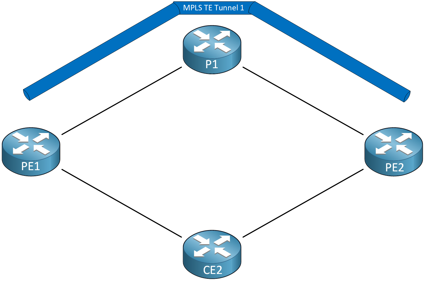
When you have a TE tunnel and use something like autoroute to use it in your routing table, you’ll notice that the router installs the tunnel as the next hop for the tailend router and any destinations behind it.
It’s impossible to load balance traffic between your IGP and a TE tunnel to the tailend router. You can’t do this because if you could, it would be impossible to route traffic down a TE tunnel that follows a suboptimal path. Here is an example:

PE1 is the headend router. PE2 is the tailend router. To get from PE1 to PE2, we have three paths:
- TE Tunnel:
- PE1 > P1 > PE2
- IGP:
- PE1 > P1 > PE2
- PE1 > CE2 > PE2
When we use the default IGP metric, these three paths have the same metric.
If PE1 didn’t prefer the TE tunnel, it would load balance traffic using these three paths. The headend router would send only 33% of the traffic through the TE tunnel.
If you want to load balance traffic to your tailend router, you’ll have to use multiple TE tunnels. This works and even supports unequal cost-load balancing.
What is possible is that you can load balance traffic between your IGP and TE tunnel to destinations behind the tailend router. In this lesson, I’ll demonstrate how this works.
Configuration
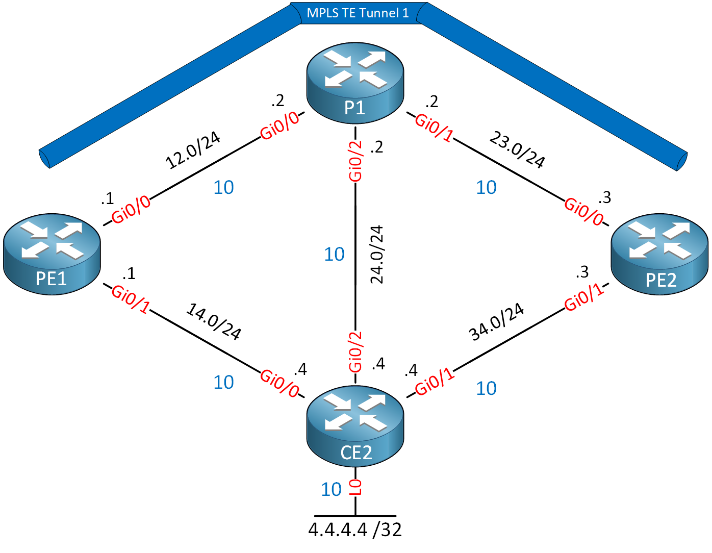
Here is our topology:

PE1 is the headend router. PE2 is our tailend router. I configured an explicit path so the tunnel goes through P1. We have two links that are not enabled for MPLS:
- PE1 – CE2
- P1 – CE2
These two links are only advertised in the IGP (IS-IS). All links have the default IS-IS metric of 10. Our goal is to load balance traffic from PE1 to CE2’s loopback interface using the TE tunnel and IGP links.
All routers use IOSv Software (VIOS-ADVENTERPRISEK9-M), Version 15.9(3)M6on all routers.
- Configurations
- CE2
- P1
- PE1
- PE2
Want to take a look for yourself? Here you will find the startup configuration of each device.
Let’s make sure the tunnel is up:
PE1#show mpls traffic-eng tunnels Tunnel 1

Name: PE1_t1                              (Tunnel1) Destination: 3.3.3.3
  Status:
    Admin: up         Oper: up     Path: valid       Signalling: connected
    path option 1, type explicit INCLUDE_P1 (Basis for Setup, path weight 10)

  Config Parameters:
    Bandwidth: 750      kbps (Global)  Priority: 7  7   Affinity: 0x0/0xFFFF
    Metric Type: TE (default)
    AutoRoute:  enabled   LockDown: disabled  Loadshare: 750      bw-based
    auto-bw: disabled
  Active Path Option Parameters:
    State: explicit path option 1 is active
    BandwidthOverride: disabled  LockDown: disabled  Verbatim: disabled


  InLabel  :  -
  OutLabel : GigabitEthernet0/0, 16
  RSVP Signalling Info:
       Src 1.1.1.1, Dst 3.3.3.3, Tun_Id 1, Tun_Instance 13
    RSVP Path Info:
      My Address: 192.168.12.1
      Explicit Route: 192.168.12.2 2.2.2.2
      Record   Route:   NONE
      Tspec: ave rate=750 kbits, burst=1000 bytes, peak rate=750 kbits
    RSVP Resv Info:
      Record   Route:   NONE
      Fspec: ave rate=750 kbits, burst=1000 bytes, peak rate=750 kbits
  Shortest Unconstrained Path Info:
    Path Weight: 20 (TE)
    Explicit Route: 192.168.12.1 192.168.12.2 192.168.23.2 192.168.23.3
                    3.3.3.3
  History:
    Tunnel:
      Time since created: 12 minutes, 7 seconds
      Time since path change: 11 minutes, 24 seconds
      Number of LSP IDs (Tun_Instances) used: 13
    Current LSP:
      Uptime: 11 minutes, 24 seconds
The tunnel is connected. You can see the explicit route and that autoroute is enabled. Let’s look at the routing table of PE1:
PE1#show ip route isis

Gateway of last resort is not set

      2.0.0.0/32 is subnetted, 1 subnets
i L2     2.2.2.2 [115/20] via 192.168.12.2, 00:12:02, GigabitEthernet0/0
      3.0.0.0/32 is subnetted, 1 subnets
i L2     3.3.3.3 [115/30] via 3.3.3.3, 00:09:50, Tunnel1
      4.0.0.0/32 is subnetted, 1 subnets
i L2     4.4.4.4 [115/20] via 192.168.14.4, 00:09:50, GigabitEthernet0/1
i L2  192.168.23.0/24 [115/20] via 192.168.12.2, 00:09:50, GigabitEthernet0/0
i L2  192.168.24.0/24 [115/20] via 192.168.14.4, 00:07:38, GigabitEthernet0/1
                      [115/20] via 192.168.12.2, 00:07:38, GigabitEthernet0/0
i L2  192.168.34.0/24 [115/20] via 192.168.14.4, 00:09:50, GigabitEthernet0/1
In the output above, we see:
- We only use tunnel 1 to reach the tailend router (3.3.3.3). The metric is 30.
- We use the direct IGP path to CE2 to reach the loopback interface of CE2 (4.4.4.4). The metric is 20.
There are three paths to get from PE1 to CE2:
- TE Tunnel:
- PE1 > PE2 > CE2
- IGP:
- PE1 > CE2
- PE1 > P1 > CE2
Let’s see if we can play with the IS-IS metric so that PE1 load balances traffic on these three paths to reach CE2. The metric of the TE tunnel is the same as the shortest IGP path. To get from PE1 to PE2, we must cross two GigabitEthernet links. That’s a metric of 20.
To get from PE2 to CE2’s loopback interface, we must cross one GigabitEthernet link (10) and the loopback of CE2 (10) for a total metric of 20. The total metric through the TE tunnel to CE2’s loopback is 40.
- Unit 1: Introduction
- Unit 2: LDP (Label Distribution Protocol)
- Unit 3: MPLS VPN
- VRFs (Virtual Routing and Forwarding)
- MPLS L3 VPN Explained
- MPLS L3 VPN Configuration
- MPLS L3 VPN BGP Allow AS in
- MPLS L3 VPN BGP AS Override
- MPLS L3 VPN PE-CE RIP
- MPLS L3 VPN PE-CE EIGRP
- MPLS L3 VPN PE-CE OSPF
- MPLS L3 VPN PE-CE OSPF Default Route
- MPLS L3 VPN PE-CE OSPF Global Default Route
- MPLS L3 VPN PE-CE OSPF Sham Link
- VRF Lite Route Leaking
- MPLS VPN Extranet Route Leaking
- MPLS VPN VRF Export Map
- MPLS VPN VRF Import Map
- MPLS over FlexVPN
- Unit 4: MPLS L2 Encapsulation
- Unit 5: IPv6 MPLS
- Unit 6: MPLS Traffic Engineering (TE)
- Introduction to MPLS Traffic Engineering (TE)
- MPLS Traffic Engineering (TE) IS-IS Configuration
- MPLS Traffic Engineering (TE) OSPF Configuration
- MPLS TE RSVP-TE
- MPLS TE Static Routes
- MPLS TE Policy Based Routing (PBR)
- MPLS TE Autoroute Announce
- MPLS TE Autoroute Destination
- MPLS TE Autoroute Metric
- MPLS TE Unequal Cost Load Balancing
- MPLS TE Load Balancing between IGP and TE
- MPLS TE Forwarding Adjacency
- MPLS TE Path Options Explicit
- MPLS TE Class-Based Tunnel Selection (CBTS)
- MPLS TE Metric
- MPLS TE Setup and Hold Priority
- MPLS TE Attribute Flag and Affinity
- MPLS TE Reoptimization
- MPLS TE Fast Reroute (FRR)
- MPLS TE Fast Reroute Path Link Protection
- MPLS TE Fast Reroute Path Node Protection
- MPLS TE FRR RSVP Hello Support
- MPLS TE DiffServ Aware (DS-TE) Traditional
- MPLS TE Diffserv-Aware (DS-TE) IETF Mode
- MPLS VPN over MPLS TE Tunnels
- MPLS TE Per VRF TE tunnel