In this lesson we’ll take a look how to configure a MPLS Layer 3 VPN PE-CE scenario. Here’s the topology I will use:
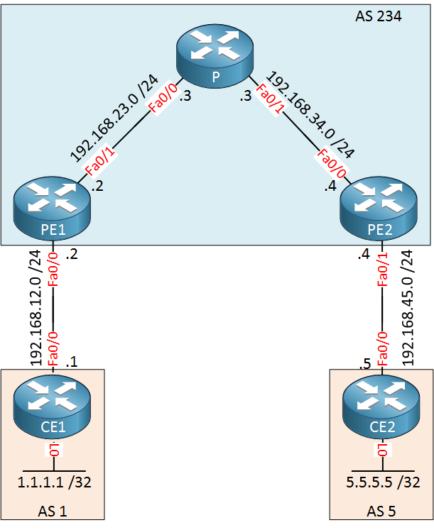
Above we have five routers where AS 234 is the service provider. There’s one customer with two sites, AS 1 and AS 5. Our customer wants to exchange 1.1.1.1 /32 and 5.5.5.5 /32 between its sites using BGP. To achieve this, we’ll have to do a couple of things:
- Configure IGP and LDP within the service provider network.
- Configure VRFs on the PE routers.
- Configure IBGP between the PE routers.
- Configure BGP between the PE and CE routers.
There are a lot of difference pieces in the MPLS puzzle to make this work. Instead of configuring everything at once and praying that it will work, we’ll build this network step-by-step. At each step, I’ll show you how to verify that it’s working before we continue with the next step.
Having said that, let’s get started!
Configuration
IGP and LDP
First we will configure the service provider network. On the PE1, P and PE2 routers we will create a loopback interface that will be advertised in OSPF. LDP will then uses the addresses as the transport address for the TCP connection. Let’s add those interfaces and enable OSPF:
PE1(config)#interface loopback 0
PE1(config-if)#ip address 2.2.2.2 255.255.255.255P(config)#interface loopback 0
P(config-if)#ip address 3.3.3.3 255.255.255.255PE2(config)#interface loopback 0
PE2(config-if)#ip address 4.4.4.4 255.255.255.255Now we will configure OSPF to advertise all interfaces in the service provider network:
PE1(config)#router ospf 1
PE1(config-router)#network 192.168.23.0 0.0.0.255 area 0
PE1(config-router)#network 2.2.2.2 0.0.0.0 area 0P(config)#router ospf 1
P(config-router)#network 192.168.23.0 0.0.0.255 area 0
P(config-router)#network 192.168.34.0 0.0.0.255 area 0
P(config-router)#network 3.3.3.3 0.0.0.0 area 0PE2(config)#router ospf 1
PE2(config-router)#network 192.168.34.0 0.0.0.255 area 0
PE2(config-router)#network 4.4.4.4 0.0.0.0 area 0And let’s enable LDP on all internal interfaces:
PE1(config)#interface FastEthernet 0/1
PE1(config-if)#mpls ipP(config)#interface FastEthernet 0/0
P(config-if)#mpls ip
P(config)#interface FastEthernet 0/1
P(config-if)#mpls ipPE2(config)#interface FastEthernet 0/0
PE2(config-if)#mpls ipThat takes care of that. Let’s see if MPLS is enabled:
PE1#show mpls interfaces
Interface              IP            Tunnel   BGP Static Operational
FastEthernet0/1 Yes (ldp) No No No YesP#show mpls interfaces
Interface IP Tunnel BGP Static Operational
FastEthernet0/0 Yes (ldp) No No No Yes
FastEthernet0/1 Yes (ldp) No No No YesPE2#show mpls interfaces
Interface IP Tunnel BGP Static Operational
FastEthernet0/0 Yes (ldp) No No No YesThat’s looking good to me. Do we have any LDP neighbors?
P#show mpls ldp neighbor
    Peer LDP Ident: 2.2.2.2:0; Local LDP Ident 3.3.3.3:0
	TCP connection: 2.2.2.2.646 - 3.3.3.3.55065
	State: Oper; Msgs sent/rcvd: 10/11; Downstream
	Up time: 00:02:39
	LDP discovery sources:
	  FastEthernet0/0, Src IP addr: 192.168.23.2
        Addresses bound to peer LDP Ident:
          192.168.12.2    192.168.23.2    2.2.2.2
    Peer LDP Ident: 4.4.4.4:0; Local LDP Ident 3.3.3.3:0
	TCP connection: 4.4.4.4.52817 - 3.3.3.3.646
	State: Oper; Msgs sent/rcvd: 10/11; Downstream
	Up time: 00:02:02
	LDP discovery sources:
	  FastEthernet0/1, Src IP addr: 192.168.34.4
        Addresses bound to peer LDP Ident:
          192.168.34.4    192.168.45.4    4.4.4.4
Our P router in the middle has two neighbors so we know that LDP is working. Just to be sure, let’s check if we have connectivity between PE1 and PE2:
PE1#ping 4.4.4.4 source loopback 0
Type escape sequence to abort.
Sending 5, 100-byte ICMP Echos to 4.4.4.4, timeout is 2 seconds:
Packet sent with a source address of 2.2.2.2
!!!!!
Success rate is 100 percent (5/5), round-trip min/avg/max = 1/2/4 ms
A quick ping tells us that it’s working. Are we switching based on labels though? Let’s do a trace to find out:
PE1#traceroute 4.4.4.4 source loopback 0
Type escape sequence to abort.
Tracing the route to 4.4.4.4
VRF info: (vrf in name/id, vrf out name/id)
  1 192.168.23.3 [MPLS: Label 17 Exp 0] 0 msec 0 msec 4 msec
  2 192.168.34.4 0 msec 0 msec *
Above you can see that we are using a label for the packet from PE1 to PE2. The P router is popping the label (penultimate hop popping) so PE1 receives a normal IP packet. So far, this is looking good.
VRF on the PE routers
Since we want our customer routes separated from the service provider’s routes, we’ll have to create some VRFs. Here’s how it’s done:
PE1(config)#ip vrf CUSTOMERFirst I will create a VRF called CUSTOMER. The next step will be configuring a RD (Route Distinguisher):
PE1(config-vrf)#rd ?
  ASN:nn or IP-address:nn  VPN Route Distinguisher
The RD is to make sure that all prefixes are unique. The customer prefix + RD together are a VPNv4 route. I’ll pick something simple:
PE1(config-vrf)#rd 1:1Our RD will be 1:1. The next item to configure is the RT (Route Target). This defines where we will import and export our VPNv4 routes. I want to make sure that all routes from CE1 and CE2 will be exchanged:
PE1(config-vrf)#route-target both 1:1I will use RT value 1:1 and use parameter both. This means that all routes of this VRF will be imported and exported.
I used the same value (1:1) for the RD and RT, keep in mind that these are two different things…don’t mix them up!
Here’s what the VRF now looks like:
PE1#show run | begin vrf
ip vrf CUSTOMER
 rd 1:1
 route-target export 1:1
 route-target import 1:1
After creating the VRF globally, we have to assign the interface that is facing the customer to the VRF:
PE1(config)#interface FastEthernet 0/0
PE1(config-if)#ip vrf forwarding CUSTOMER
% Interface FastEthernet0/0 IPv4 disabled and address(es) removed due to enabling VRF CUSTOMER
Once you add an interface to a VRF, Cisco IOS will remove its IP address. Let’s add it again:
PE1(config-if)#ip address 192.168.12.2 255.255.255.0The VRF configuration of PE1 is now complete. We’ll configure the exact same thing on PE2:
PE2(config)#ip vrf CUSTOMER
PE2(config-vrf)#rd 1:1
PE2(config-vrf)#route-target export 1:1
PE2(config-vrf)#route-target import 1:1

PE2(config)#interface FastEthernet 0/1
PE2(config-if)#ip vrf forwarding CUSTOMER
PE2(config-if)#ip address 192.168.45.4 255.255.255.0
The VRFs are now configured. If you want to reach the CE1 or CE2 routers then you’ll have to use the VRFs from now on:
PE1#ping vrf CUSTOMER 192.168.12.1
Type escape sequence to abort.
Sending 5, 100-byte ICMP Echos to 192.168.12.1, timeout is 2 seconds:
!!!!!
Success rate is 100 percent (5/5), round-trip min/avg/max = 1/1/4 msPE2#ping vrf CUSTOMER 192.168.45.5
Type escape sequence to abort.
Sending 5, 100-byte ICMP Echos to 192.168.45.5, timeout is 2 seconds:
!!!!!
Success rate is 100 percent (5/5), round-trip min/avg/max = 1/2/4 msGreat our VRFs are operational!
IBGP Configuration on PE1 and PE2
PE1 and PE2 will have to exchange VPNv4 routes through IBGP. When you configure iBGP, your routers will only exchange IPv4 unicast routes by default. Since we need the PE routers to exchange VPNv4 routes, we’ll have to activate an additional address-family:
- Unit 1: Introduction
- Unit 2: LDP (Label Distribution Protocol)
- Unit 3: MPLS VPN
- VRFs (Virtual Routing and Forwarding)
- MPLS L3 VPN Explained
- MPLS L3 VPN Configuration
- MPLS L3 VPN BGP Allow AS in
- MPLS L3 VPN BGP AS Override
- MPLS L3 VPN PE-CE RIP
- MPLS L3 VPN PE-CE EIGRP
- MPLS L3 VPN PE-CE OSPF
- MPLS L3 VPN PE-CE OSPF Default Route
- MPLS L3 VPN PE-CE OSPF Global Default Route
- MPLS L3 VPN PE-CE OSPF Sham Link
- VRF Lite Route Leaking
- MPLS VPN Extranet Route Leaking
- MPLS VPN VRF Export Map
- MPLS VPN VRF Import Map
- MPLS over FlexVPN
- Unit 4: MPLS L2 Encapsulation
- Unit 5: IPv6 MPLS
- Unit 6: MPLS Traffic Engineering (TE)
- Introduction to MPLS Traffic Engineering (TE)
- MPLS Traffic Engineering (TE) IS-IS Configuration
- MPLS Traffic Engineering (TE) OSPF Configuration
- MPLS TE RSVP-TE
- MPLS TE Static Routes
- MPLS TE Policy Based Routing (PBR)
- MPLS TE Autoroute Announce
- MPLS TE Autoroute Destination
- MPLS TE Autoroute Metric
- MPLS TE Unequal Cost Load Balancing
- MPLS TE Load Balancing between IGP and TE
- MPLS TE Forwarding Adjacency
- MPLS TE Path Options Explicit
- MPLS TE Class-Based Tunnel Selection (CBTS)
- MPLS TE Metric
- MPLS TE Setup and Hold Priority
- MPLS TE Attribute Flag and Affinity
- MPLS TE Reoptimization
- MPLS TE Fast Reroute (FRR)
- MPLS TE Fast Reroute Path Link Protection
- MPLS TE Fast Reroute Path Node Protection
- MPLS TE FRR RSVP Hello Support
- MPLS TE DiffServ Aware (DS-TE) Traditional
- MPLS TE Diffserv-Aware (DS-TE) IETF Mode
- MPLS VPN over MPLS TE Tunnels
- MPLS TE Per VRF TE tunnel