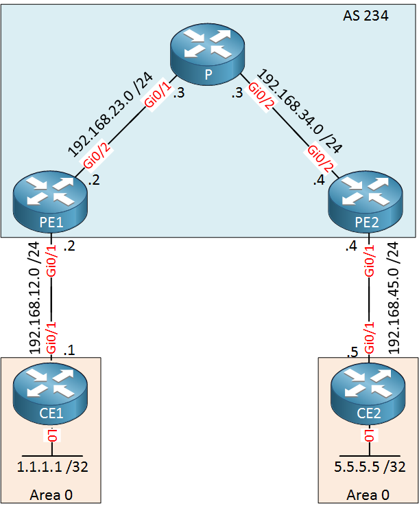
OSPF Sham Links are required when you try to use a backdoor link between two CE routers in an MPLS VPN PE CE scenario where you use OSPF as the PE-CE routing protocol. This is best explained with an example, take a look at the following topology:

Above we have an MPLS VPN topology where we use OSPF as the PE-CE routing protocol. CE1 and CE2 each have a loopback interface that is advertised in OSPF area 0. Right now, the MPLS backbone is the only way for the CE routers to reach each other.
- Configurations
- CE1
- CE2
- P
- PE1
- PE2
Want to take a look for yourself? Here you will find the startup configuration of each device.
Let’s take a look at the routing tables of our CE routers:
CE1#show ip route ospf

      5.0.0.0/32 is subnetted, 1 subnets
O IA     5.5.5.5 [110/3] via 192.168.12.2, 00:09:22, GigabitEthernet0/1
O IA 192.168.45.0/24 [110/2] via 192.168.12.2, 00:09:22, GigabitEthernet0/1CE2#show ip route ospf
1.0.0.0/32 is subnetted, 1 subnets
O IA 1.1.1.1 [110/3] via 192.168.45.4, 00:09:36, GigabitEthernet0/1
O IA 192.168.12.0/24 [110/2] via 192.168.45.4, 00:09:36, GigabitEthernet0/1The CE routers see each other’s loopback interfaces as an inter-area route through the OSPF “super backbone”. Let’s try a traceroute just to be sure that our CE routers can reach each other:
CE1#traceroute 5.5.5.5 source 1.1.1.1
Type escape sequence to abort.
Tracing the route to 5.5.5.5
VRF info: (vrf in name/id, vrf out name/id)
  1 192.168.12.2 5 msec 7 msec 5 msec
  2 192.168.23.3 [MPLS: Labels 17/19 Exp 0] 9 msec 11 msec 9 msec
  3 192.168.45.4 [MPLS: Label 19 Exp 0] 9 msec 12 msec 10 msec
  4 192.168.45.5 9 msec 10 msec *
Configuration
Backdoor Link
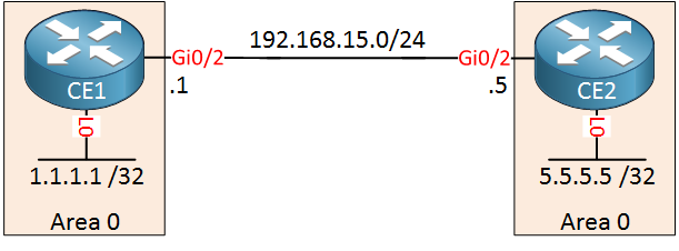
Time to mess things up. Let’s add a backdoor link between CE1 and CE2. This could be a backup link that you want to use in case the MPLS VPN provider has issues:

Let’s enable OSPF on this interface and advertise it in area 0:
CE1(config)#router ospf 1
CE1(config-router)#network 192.168.15.0 0.0.0.255 area 0CE2(config)#router ospf 1
CE2(config-router)#network 192.168.15.0 0.0.0.255 area 0The total cost through the MPLS VPN network is 4. Let’s increase the metric for our backdoor link to 100:
CE1 & CE2
(config)#interface GigabitEthernet 0/2
(config-if)#ip ospf cost 100
Let’s see which interface our CE routers now want to use:
CE1#show ip route ospf

      5.0.0.0/32 is subnetted, 1 subnets
O        5.5.5.5 [110/101] via 192.168.15.5, 00:00:22, GigabitEthernet0/2
O 192.168.45.0/24 [110/101] via 192.168.15.5, 00:00:22, GigabitEthernet0/2CE2#show ip route ospf
1.0.0.0/32 is subnetted, 1 subnets
O 1.1.1.1 [110/101] via 192.168.15.1, 00:00:27, GigabitEthernet0/2
O 192.168.12.0/24 [110/101] via 192.168.15.1, 00:00:27, GigabitEthernet0/2Despite the higher cost, CE1 and CE2 prefer the backdoor link. This is because OSPF always prefers intra-area routes over inter-area routes.
CE1#traceroute 5.5.5.5 source 1.1.1.1
Type escape sequence to abort.
Tracing the route to 5.5.5.5
VRF info: (vrf in name/id, vrf out name/id)
  1 192.168.15.5 7 msec 4 msec *
OSPF Sham Link
The only way to fix this is to advertise the routes that are learned through the MPLS VPN network as intra-area routes. We can do this with the OSPF sham link. The sham link is a logical link, similar to a virtual link. It allows you to create a point-to-point connection between the two PE routers. The PE routers are then able to flood LSAs across the MPLS VPN backbone. You don’t have to configure anything on the CE routers.
The sham link is established between two IP addresses that have to be in the VRF of the customer. To achieve this, we will create a new loopback interface on each PE router which is advertised in BGP:
- PE1: 22.22.22.22/32
- PE2: 44.44.44.44/32
Let’s start with PE1:
PE1(config)#interface loopback 1
PE1(config-if)#ip vrf forwarding CUSTOMER
PE1(config-if)#ip address 22.22.22.22 255.255.255.255
Let’s advertise this IP address in BGP:
- Unit 1: Introduction
- Unit 2: LDP (Label Distribution Protocol)
- Unit 3: MPLS VPN
- VRFs (Virtual Routing and Forwarding)
- MPLS L3 VPN Explained
- MPLS L3 VPN Configuration
- MPLS L3 VPN BGP Allow AS in
- MPLS L3 VPN BGP AS Override
- MPLS L3 VPN PE-CE RIP
- MPLS L3 VPN PE-CE EIGRP
- MPLS L3 VPN PE-CE OSPF
- MPLS L3 VPN PE-CE OSPF Default Route
- MPLS L3 VPN PE-CE OSPF Global Default Route
- MPLS L3 VPN PE-CE OSPF Sham Link
- VRF Lite Route Leaking
- MPLS VPN Extranet Route Leaking
- MPLS VPN VRF Export Map
- MPLS VPN VRF Import Map
- MPLS over FlexVPN
- Unit 4: MPLS L2 Encapsulation
- Unit 5: IPv6 MPLS
- Unit 6: MPLS Traffic Engineering (TE)
- Introduction to MPLS Traffic Engineering (TE)
- MPLS Traffic Engineering (TE) IS-IS Configuration
- MPLS Traffic Engineering (TE) OSPF Configuration
- MPLS TE RSVP-TE
- MPLS TE Static Routes
- MPLS TE Policy Based Routing (PBR)
- MPLS TE Autoroute Announce
- MPLS TE Autoroute Destination
- MPLS TE Autoroute Metric
- MPLS TE Unequal Cost Load Balancing
- MPLS TE Load Balancing between IGP and TE
- MPLS TE Forwarding Adjacency
- MPLS TE Path Options Explicit
- MPLS TE Class-Based Tunnel Selection (CBTS)
- MPLS TE Metric
- MPLS TE Setup and Hold Priority
- MPLS TE Attribute Flag and Affinity
- MPLS TE Reoptimization
- MPLS TE Fast Reroute (FRR)
- MPLS TE Fast Reroute Path Link Protection
- MPLS TE Fast Reroute Path Node Protection
- MPLS TE FRR RSVP Hello Support
- MPLS TE DiffServ Aware (DS-TE) Traditional
- MPLS TE Diffserv-Aware (DS-TE) IETF Mode
- MPLS VPN over MPLS TE Tunnels
- MPLS TE Per VRF TE tunnel