OSPF Loop-Free Alternate (LFA) Fast Reroute (FRR) is a technique where our router is able to pre-install a backup next hop in the routing table and CEF table, making failover very fast (< 50 MS). In some topologies, however, this is not possible. Before you continue with this lesson, make sure you are very familiar with MPLS VPN.
Let’s start with a quick example:
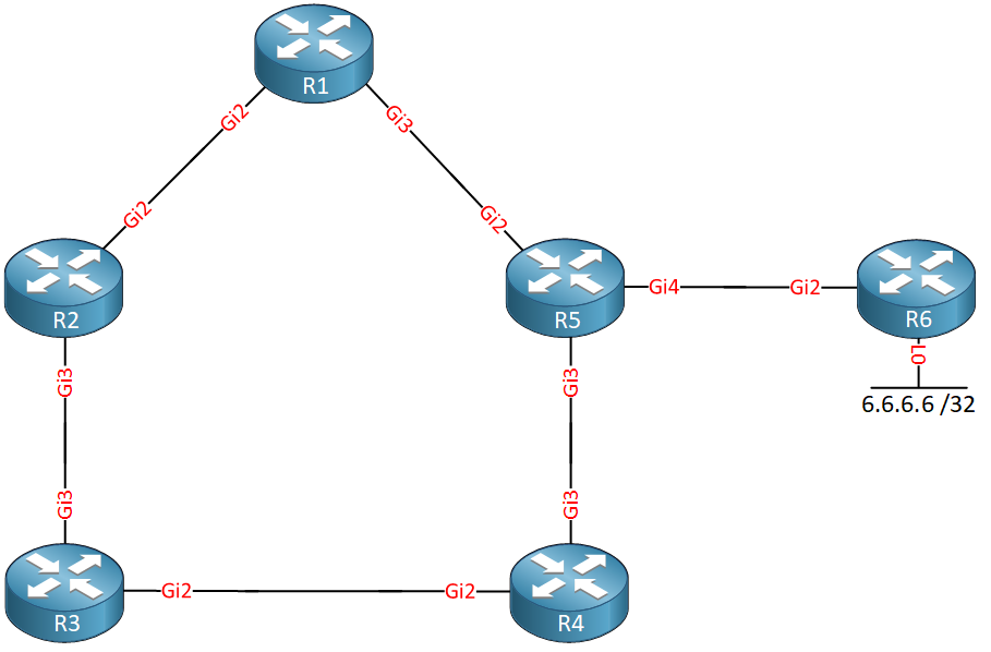
Above we have a bunch of routers. Behind R6 we have a loopback interface with IP address 6.6.6.6/32. We use Gigabit interfaces everywhere with the default cost. Let’s focus on R1.
R1 has two paths to get to 6.6.6.6/32:
- R1 > R5 > R6
- R1 > R2 > R3 > R4 > R5 > R6
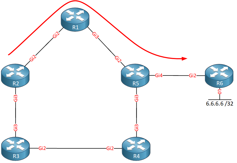
The path through R5 is the shortest path, so R5 becomes our next hop. You might think that R2 could be used as a backup path, but that’s not the case. Why? Because R2’s shortest path is through R1:
R3 however, is using R4 as its next hop:
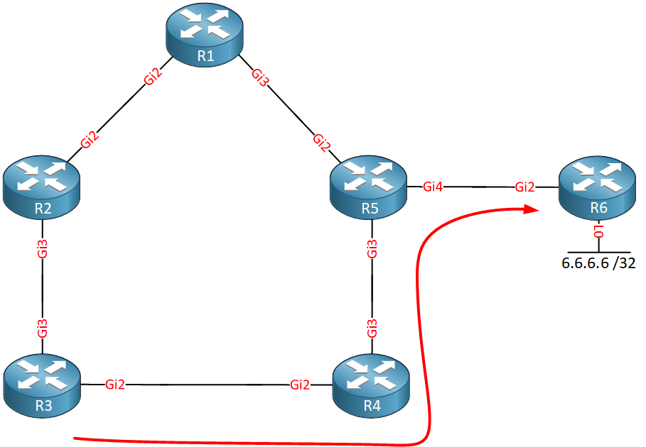
If only there were a way so we could use R3 as a next hop…bypassing R2. Luckily, there is! We can use tunneling to get directly from R1 to R3, bypassing R2:
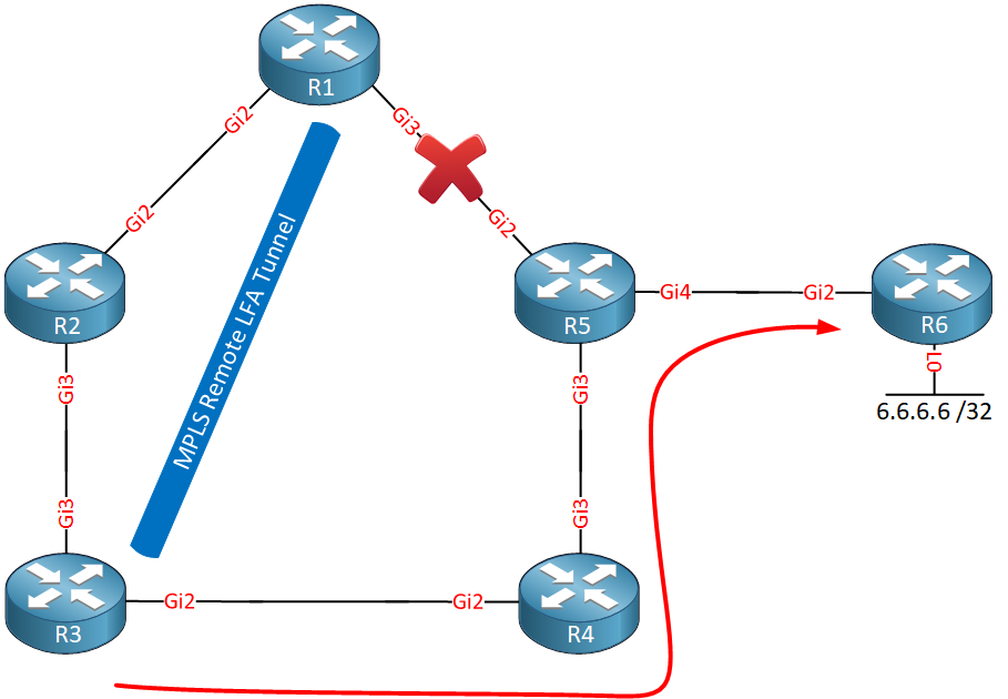
This tunneling method to a remote router to use it as an alternate backup path is called remote LFA (Loop-Free Alternate) FRR (Fast Reroute). A targeted MPLS LDP session between the two routers is used for the tunnel.
Why did R1 select R3?
To understand this, we first have to talk about some remote LFA terminology:
- P space: these are the routers that R1 can reach without using the failed link. This can be calculated by running SPT with R1 as the root. From R1’s perspective, R2 and R3 belong to the P space since it would use its Gigabit 2 interface to reach these two routers.
- Q space: these are the routers that can reach R5 without using the failed link. To figure this out, you have to run SPT with R5 as the root. R5 uses its Gigabit 3 interface to reach R3 and R4, so these two routers belong to the Q space.
- PQ node: this is the router that belongs to both the P and Q space. In our topology, R3 belongs to both the P and Q space, so this router is selected as the PQ node. The PQ node is used as the endpoint for our tunnel.
Now you know why remote LFA is needed and how the remote tunnel endpoint is selected. Let’s look at this in action.
Configuration
Here is the topology we will use:
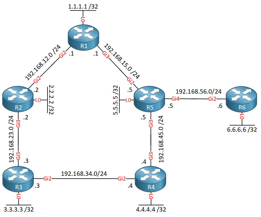
It’s the same topology as before, but I added network and IP addresses. Each router has a loopback interface which is needed because remote LFA uses a targeted LDP session between the two tunnel endpoints. All interfaces are advertised in OSPF area 0.
- Configurations
- R1
- R2
- R3
- R4
- R5
- R6
Want to take a look for yourself? Here you will find the startup configuration of each device.
The tunnel uses MPLS LDP, so the first thing we should do is enable MPLS LDP on all interfaces. You can do this with the mpls ip command on each interface or enable MPLS on all interfaces that run OSPF:
R1, R2, R3, R4, R5 & R6
(config-router)#mpls ldp autoconfig area 0
MPLS LDP forms neighbor adjacencies with directly connected neighbors, but in our case, we need an MPLS LDP neighbor adjacency between R1 and R3 who are not directly connected. By default, routers reject targeted MPLS LDP hello requests from non-directly connected routers. This is something we have to enable:
R1, R2, R3, R4, R5 & R6
(config)#mpls ldp discovery targeted-hello accept
Remote LFA also requires “regular” LFA so let’s enable this on all routers:
R1, R2, R3, R4, R5 & R6
(config)#router ospf 1
(config-router)#fast-reroute per-prefix enable area 0 prefix-priority low
(config-router)#fast-reroute keep-all-paths
Last but not least, let’s configure remote LFA:
R1, R2, R3, R4, R5 & R6
(config)#router ospf 1
(config-router)#fast-reroute per-prefix remote-lfa tunnel mpls-ldp
This command enables remote LFA and uses MPLS LDP as the tunnel protocol. Optionally, you can configure the area that you want to protect and/or set a maximum cost. We’ll keep it simple for now so this completes our configuration.
Verification
Let’s verify our work. First, let’s check R1 to see how it reaches 6.6.6.6/32:
R1#show ip route 6.6.6.6
Routing entry for 6.6.6.6/32
  Known via "ospf 1", distance 110, metric 3, type intra area
  Last update from 192.168.15.5 on GigabitEthernet3, 00:03:56 ago
  Routing Descriptor Blocks:
  * 192.168.15.5, from 6.6.6.6, 00:03:56 ago, via GigabitEthernet3
      Route metric is 3, traffic share count is 1
      Repair Path: 3.3.3.3, via MPLS-Remote-Lfa1
Above, we see that R1 uses R5 as the primary next hop but also uses R3 as a backup path via the “MPLS-Remote-Lfa1” interface. This is a new interface that R1 created. You can see it here:
R1#show ip interface brief | include MPLS
MPLS-Remote-Lfa1       192.168.12.1    YES unset  up                    up
MPLS-Remote-Lfa2       192.168.15.1    YES unset  up                    up
These interfaces are the MPLS LDP tunnels that R1 uses for remote LFA. You can take a closer look with the following command:
R1#show ip ospf fast-reroute remote-lfa tunnels

            OSPF Router with ID (1.1.1.1) (Process ID 1)

                     Area with ID (0)

                    Base Topology (MTID 0)

Interface MPLS-Remote-Lfa1
  Tunnel type: MPLS-LDP
  Tailend router ID: 3.3.3.3
  Termination IP address: 3.3.3.3
  Outgoing interface: GigabitEthernet2
  First hop gateway: 192.168.12.2
  Tunnel metric: 1
  Protects:
    192.168.15.5 GigabitEthernet3, total metric 3
Above, you see that this is the tunnel that connects to R3. Let’s take a closer look at the route to 6.6.6.6/32. Here is the CEF entry of R1:
R1#show ip cef 6.6.6.6
6.6.6.6/32
  nexthop 192.168.15.5 GigabitEthernet3 label [20|20]-(local:20)
    repair: attached-nexthop 3.3.3.3 MPLS-Remote-Lfa1
Here we find the primary path through R1 and the backup path through R3 with their interfaces. Nothing new, since we also saw this in the output of show ip route. There is something new though that I highlighted, the labels. The first label (20) is the label for the primary path, the second one (20) is for the repair path.
Let’s take a closer look at these labels:
R1#show mpls forwarding-table 6.6.6.6
Local      Outgoing   Prefix           Bytes Label   Outgoing   Next Hop
Label      Label      or Tunnel Id     Switched      interface
20         20         6.6.6.6/32       0             Gi3        192.168.15.5
R1 has selected 20 as the label to reach 6.6.6.6 through R5. R3 selected the same label for this destination:
R3#show mpls forwarding-table 6.6.6.6
Local      Outgoing   Prefix           Bytes Label   Outgoing   Next Hop
Label      Label      or Tunnel Id     Switched      interface
20         20         6.6.6.6/32       0             Gi2        192.168.34.4
The label that R3 uses is advertised to R1 directly; you can also check this from R1. First, let’s verify that R1 and R3 are neighbors:
R1#show mpls ldp neighbor 3.3.3.3
    Peer LDP Ident: 3.3.3.3:0; Local LDP Ident 1.1.1.1:0
        TCP connection: 3.3.3.3.36475 - 1.1.1.1.646
        State: Oper; Msgs sent/rcvd: 22/23; Downstream
        Up time: 00:04:24
        LDP discovery sources:
          Targeted Hello 1.1.1.1 -> 3.3.3.3, active, passive
        Addresses bound to peer LDP Ident:
          192.168.34.3    192.168.23.3    3.3.3.3
Here’s how you can verify that R1 learned that R3 uses label 20 for destination 6.6.6.6/32:
R1#show mpls ldp bindings neighbor 3.3.3.3 6.6.6.6 32
  lib entry: 6.6.6.6/32, rev 14
        remote binding: lsr: 3.3.3.3:0, label: 20
As long as the link between R1 and R5 remains, R1 uses the link to R5 to reach 6.6.6.6/32. The traffic is then label switched using label 20.
When the link between R1 and R5 fails, we switch to R3. Traffic to R3 is also label switched, so that’s one additional label to check:
R1#show mpls ldp bindings 3.3.3.3 32
  lib entry: 3.3.3.3/32, rev 8
        local binding:  label: 17
When R1 sends an IP packet through the backup path. It first adds an inner label (20) and then an outer label (17). The outer label is used to reach R3. When R3 receives the packet, it looks at the inner label, checks its forwarding table and forwards the packet towards the destination.
- Configurations
- R1
- R2
- R3
- R4
- R5
- R6
Want to take a look for yourself? Here you will find the final configuration of each device.
Conclusion
You have now learned:
- Why you can’t always use “regular” remote LFA in some topologies.
- How remote LFA FRR uses a remote router as a backup path by tunneling.
- How to configure remote LFA FRR.
- How to verify the repair path and backup next hops that are used.
- How to verify the labels that are used for forwarding.
Unit 1: Introduction to OSPF
- Introduction to OSPF
- Basic OSPF Configuration
- OSPF Multi Area Configuration
- OSPF Reference Bandwidth
- OSPF Plain Text Authentication
- OSPF MD5 Authentication
- OSPF SHA-HMAC Authentication
- OSPF TTL Security Check
- OSPF Default Route
Unit 2: OSPF Neighbor Adjacency
- OSPF LSA Types
- OSPF LSAs and LSDB Flooding
- OSPF Hello and Dead Interval
- OSPF Router ID
- OSPF Packets and Neighbor Discovery
- OSPF DR/BDR Election
- OSPF Passive Interface
- Troubleshooting OSPF Neighbor Adjacency
Unit 3: OSPF Network Types
- OSPF Non-Broadcast Network Type
- OSPF Broadcast Network Type
- OSPF Point-to-Multipoint Network Type
- OSPF Point-to-Multipoint Non-Broadcast Network Type
- OSPF Point-to-Point Network Type
- OSPF Next Hop with Network Types
Unit 4: OSPF Stub Areas
- Introduction to OSPF Stub Areas
- How to configure OSPF Stub Area
- How to configure OSPF Totally Stub
- How to configure OSPF NSSA (Not So Stubby) Area
- How to configure OSPF Totally NSSA (Not So Stubby) Area
- OSPF NSSA P-bit explained
Unit 5: Advanced OSPF Topics
- OSPF Summarization
- OSPF Distribute-List Filtering
- OSPF LSA Type 3 Filtering
- OSPF LSA Type 5 Filtering
- OSPF Virtual Link
- OSPF Virtual Link Authentication
- OSPF Path Selection Explained
- How to read the OSPF Database
- OSPFv3 for IPv4
- Troubleshooting OSPF Route Advertisement
- OSPF SPF Scheduling and Throttling
- OSPF LSA Throttling
- OSPF Incremental SPF
- OSPF Prefix Suppression
- OSPF Stub Router
- OSPF Graceful Shutdown
- OSPF Graceful Restart
- OSPF Loop-Free Alternate (LFA) Fast Reroute (FRR)
- OSPF Remote Loop-Free Alternate (LFA) Fast Reroute (FRR)