If you studied Cisco’s CCNA you have learned that when you use OSPF all the areas have to be directly connected to the backbone area. Is this really true? Areas have to be connected to the backbone area but if they aren’t we can fix it with a virtual link.
Let me show you an example:
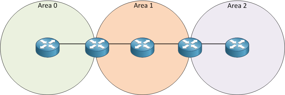
Look at my picture above. We have three areas and on the left side is area 0. Area 2 is behind area 1. Normally this is not going to work since area 2 has to be directly connected to area 0. We can make this work by using a virtual link. By using a virtual link we can extend area 0 through area 1 so area 2 will be “directly connected” to area 0. Let’s take a look at how a virtual link can solve this problem:
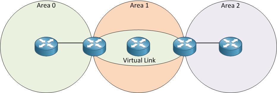
This is basically how a virtual link works. It’s like a tunnel through area 1 to reach area 2. This way area 2 will be directly connected. Now let me show you how to configure a virtual link:
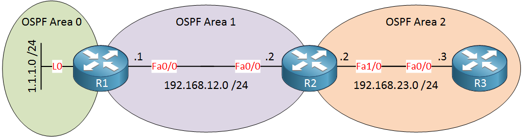
In the example above area 2 is not directly connected to area 0 so we’ll have to use a virtual link between routers R1 and R2, here’s how we do it:
R1(config)#router ospf 1
R1(config-router)#network 1.1.1.0 0.0.0.255 area 0
R1(config-router)#network 192.168.12.0 0.0.0.255 area 1 R2(config)#router ospf 1
R2(config-router)#network 192.168.12.0 0.0.0.255 area 1
R2(config-router)#network 192.168.23.0 0.0.0.255 area 2R3(config)#router ospf 1
R3(config-router)#network 192.168.23.0 0.0.0.255 area 2I’ll start with a default OSPF configuration.
R1(config)#router ospf 1
R1(config-router)#area 1 virtual-link 192.168.23.2R2(config)#router ospf 1
R2(config-router)#area 1 virtual-link 1.1.1.1We configure the virtual link between ABRs and we use the area virtual-link command. First, you need to specify the area where we need the virtual link which is area 1 in my example. The second step is to configure the OSPF router ID of the other ABR. Keep this in mind…you need to configure the OSPF router ID and NOT the IP address of the ABR. If everything is OK area 2 will be directly connected to area 0 through our virtual link.
R1# %OSPF-5-ADJCHG Process 1, Nbr 192.168.23.2 on OSPF_VL0 from LOADING to FULL, Loading DoneR2# %OSPF-5-ADJCHG: Process 1, Nbr 1.1.1.1 on OSPF_VL0 from LOADING to FULL, Loading DoneYou will see the message above that tells us the virtual link is established.
R1#show ip ospf virtual-links
Virtual Link OSPF_VL0 to router 192.168.23.2 is up
  Run as demand circuit
  DoNotAge LSA allowed.
  Transit area 1, via interface FastEthernet0/0, Cost of using 1
  Transmit Delay is 1 sec, State POINT_TO_POINT,
  Timer intervals configured, Hello 10, Dead 40, Wait 40, Retransmit 5
    Hello due in 00:00:06
    Adjacency State FULL (Hello suppressed)
    Index 1/2, retransmission queue length 0, number of retransmission 0
    First 0x0(0)/0x0(0) Next 0x0(0)/0x0(0)
    Last retransmission scan length is 0, maximum is 0
Last retransmission scan time is 0 msec, maximum is 0 msecR2#show ip ospf virtual-links
Virtual Link OSPF_VL0 to router 1.1.1.1 is up
Run as demand circuit
DoNotAge LSA allowed.
Transit area 1, via interface FastEthernet0/0, Cost of using 1
Transmit Delay is 1 sec, State POINT_TO_POINT,
Timer intervals configured, Hello 10, Dead 40, Wait 40, Retransmit 5
Hello due in 00:00:05
Adjacency State FULL (Hello suppressed)
Index 1/3, retransmission queue length 0, number of retransmission 0
First 0x0(0)/0x0(0) Next 0x0(0)/0x0(0)
Last retransmission scan length is 0, maximum is 0
Last retransmission scan time is 0 msec, maximum is 0 msecYou can use the show ip ospf virtual-links command to check if your virtual link is working.
R1#show ip ospf database

            OSPF Router with ID (1.1.1.1) (Process ID 1)

		Router Link States (Area 0)

Link ID         ADV Router      Age         Seq#       Checksum Link count
1.1.1.1         1.1.1.1         189         0x80000004 0x00E333 2
192.168.23.2 192.168.23.2 1 (DNA) 0x80000002 0x009816 1R2#show ip ospf database
OSPF Router with ID (192.168.23.2) (Process ID 1)
Router Link States (Area 0)
Link ID ADV Router Age Seq# Checksum Link count
1.1.1.1 1.1.1.1 1 (DNA) 0x80000004 0x00E333 2
192.168.23.2 192.168.23.2 159 0x80000002 0x009816 1If you look at the LSDB you will see that the virtual link shows up as a type 1 router LSA. You can also see DNA which means do not age.
- Configurations
- R2
- R1
- R3
Want to take a look for yourself? Here you will find the final configuration of each device.
Any other situation where we need a virtual link? What about a discontinuous backbone area? Let me show you an example:

Imagine the router on top was in area 0. Unfortunately, this router crashed and the result is that area 0 is now split into two pieces. We call this a Discontiguous area 0. We can use a virtual link through area 1 to solve this problem. Let me show you how to fix this problem. This is the topology that we will use:

The topology above has a broken area 0. We’ll configure a virtual link between routers R1 and R3 to fix it. Here’s the basic configuration:
R1(config)#router ospf 1
R1(config-router)#network 1.1.1.0 0.0.0.255 area 0
R1(config-router)#network 192.168.12.0 0.0.0.255 area 1R2(config)#router ospf 1
R2(config-router)#network 192.168.12.0 0.0.0.255 area 1
R2(config-router)#network 192.168.23.0 0.0.0.255 area 1R3(config)#router ospf 1
R3(config-router)#network 192.168.23.0 0.0.0.255 area 1
R3(config-router)#network 3.3.3.0 0.0.0.255 area 0First I’ll advertise all the networks, nothing special here.
R1#show ip ospf | include ID
 Routing Process "ospf 1" with ID 1.1.1.1
R3#show ip ospf | include ID
 Routing Process "ospf 1" with ID 192.168.23.3
I need to configure a virtual link between R1 and R3 and I’ll need to use the router IDs for this.
R1(config)#router ospf 1
R1(config-router)#area 1 virtual-link 192.168.23.3R3(config)#router ospf 1
R3(config-router)#area 1 virtual-link 1.1.1.1This is how we do it.
R1# %OSPF-5-ADJCHG: Process 1, Nbr 192.168.23.3 on OSPF_VL1 from LOADING to FULL, Loading DoneR3# %OSPF-5-ADJCHG: Process 1, Nbr 1.1.1.1 on OSPF_VL0 from LOADING to FULL, Loading DoneThe configuration is the same as my previous example. Just make sure to configure the area you have to get through and the OSPF router ID of the other ABR.
R1#show ip ospf virtual-links
Virtual Link OSPF_VL1 to router 192.168.23.3 is up
  Run as demand circuit
  DoNotAge LSA allowed.
  Transit area 1, via interface FastEthernet0/0, Cost of using 2
  Transmit Delay is 1 sec, State POINT_TO_POINT,
  Timer intervals configured, Hello 10, Dead 40, Wait 40, Retransmit 5
    Hello due in 00:00:04
    Adjacency State FULL (Hello suppressed)
    Index 1/2, retransmission queue length 0, number of retransmission 0
    First 0x0(0)/0x0(0) Next 0x0(0)/0x0(0)
    Last retransmission scan length is 0, maximum is 0
Last retransmission scan time is 0 msec, maximum is 0 msecR3#show ip ospf virtual-links
Virtual Link OSPF_VL0 to router 1.1.1.1 is up
Run as demand circuit
DoNotAge LSA allowed.
Transit area 1, via interface FastEthernet0/0, Cost of using 2
Transmit Delay is 1 sec, State POINT_TO_POINT,
Timer intervals configured, Hello 10, Dead 40, Wait 40, Retransmit 5
Hello due in 00:00:07
Adjacency State FULL (Hello suppressed)
Index 1/2, retransmission queue length 0, number of retransmission 0
First 0x0(0)/0x0(0) Next 0x0(0)/0x0(0)
Last retransmission scan length is 0, maximum is 0
Last retransmission scan time is 0 msec, maximum is 0 msecThis is how we can verify if the virtual link is up and running.
R1#show ip route  ospf | include 3.3.3.3
     3.0.0.0/32 is subnetted, 1 subnets
O 3.3.3.3 [110/3] via 192.168.12.2, 00:05:13, FastEthernet0/0R3#show ip route ospf | include 1.1.1.1
O 1.1.1.1 [110/3] via 192.168.23.2, 00:05:52, FastEthernet0/0We can also verify that 1.1.1.1 and 3.3.3.3 show up as intra-area prefixes on R1 and R3. This is because area 0 is extended through area 1.
Something many CCNP students forget is that you need to use the router ID for the virtual link, not the IP address of your OSPF neighbor.
Unit 1: Introduction to OSPF
- Introduction to OSPF
- Basic OSPF Configuration
- OSPF Multi Area Configuration
- OSPF Reference Bandwidth
- OSPF Plain Text Authentication
- OSPF MD5 Authentication
- OSPF SHA-HMAC Authentication
- OSPF TTL Security Check
- OSPF Default Route
Unit 2: OSPF Neighbor Adjacency
- OSPF LSA Types
- OSPF LSAs and LSDB Flooding
- OSPF Hello and Dead Interval
- OSPF Router ID
- OSPF Packets and Neighbor Discovery
- OSPF DR/BDR Election
- OSPF Passive Interface
- Troubleshooting OSPF Neighbor Adjacency
Unit 3: OSPF Network Types
- OSPF Non-Broadcast Network Type
- OSPF Broadcast Network Type
- OSPF Point-to-Multipoint Network Type
- OSPF Point-to-Multipoint Non-Broadcast Network Type
- OSPF Point-to-Point Network Type
- OSPF Next Hop with Network Types
Unit 4: OSPF Stub Areas
- Introduction to OSPF Stub Areas
- How to configure OSPF Stub Area
- How to configure OSPF Totally Stub
- How to configure OSPF NSSA (Not So Stubby) Area
- How to configure OSPF Totally NSSA (Not So Stubby) Area
- OSPF NSSA P-bit explained
Unit 5: Advanced OSPF Topics
- OSPF Summarization
- OSPF Distribute-List Filtering
- OSPF LSA Type 3 Filtering
- OSPF LSA Type 5 Filtering
- OSPF Virtual Link
- OSPF Virtual Link Authentication
- OSPF Path Selection Explained
- How to read the OSPF Database
- OSPFv3 for IPv4
- Troubleshooting OSPF Route Advertisement
- OSPF SPF Scheduling and Throttling
- OSPF LSA Throttling
- OSPF Incremental SPF
- OSPF Prefix Suppression
- OSPF Stub Router
- OSPF Graceful Shutdown
- OSPF Graceful Restart
- OSPF Loop-Free Alternate (LFA) Fast Reroute (FRR)
- OSPF Remote Loop-Free Alternate (LFA) Fast Reroute (FRR)