Multicast RPF (Reverse Path Forwarding)
One of the key differences between unicast and multicast is that for unicast routing, we only care about where the destination is located and how to get there. For multicast routing, we care about where the source is located. PIM (Protocol Independent Multicast) uses the unicast routing table to check what interface will be used to reach the source.
PIM will only accept multicast packets on an interface we use to reach the source. If we receive multicast packets on an interface we don’t use to reach the source, we will drop the multicast packets! This is called an RPF failure, and it’s the #1 issue why multicast isn’t working for many networking students.
Let me demonstrate this using a very simple topology:
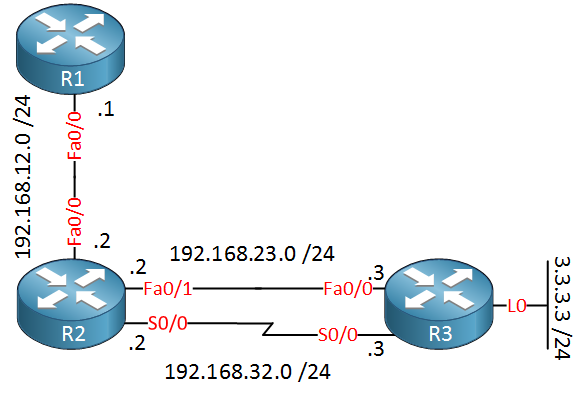
Above, you see three routers. R1 will be the source for our multicast traffic. Between R2 and R3, we have two links…a slow serial link and a FastEthernet link. R3 has a loopback interface we will use as the receiver for our multicast traffic. First, we will enable OSPF on all interfaces to have basic connectivity:
R1(config)#router ospf 1
R1(config-router)#network 0.0.0.0 255.255.255.255 area 0R2(config)#router ospf 1
R2(config-router)#network 0.0.0.0 255.255.255.255 area 0R3(config)#router ospf 1
R3(config-router)#network 0.0.0.0 255.255.255.255 area 0I will enable OSPF on all interfaces quickly using the network command above. OSPF will prefer to use the FastEthernet link and won’t use the serial link:
R2#show ip route ospf
     3.0.0.0/32 is subnetted, 1 subnets
O       3.3.3.3 [110/11] via 192.168.23.3, 00:00:02, FastEthernet0/1
As you can see we don’t use the serial link because the FastEthernet link has a lower cost. Now I’m going to configure multicast on all routers, but I will only activate it on the serial link between R2 and R3:
R1(config)#ip multicast-routing
R1(config)#interface fastEthernet 0/0
R1(config-if)#ip pim dense-mode R2(config)#ip multicast-routing
R2(config)#interface fastEthernet 0/0
R2(config-if)#ip pim dense-mode
R2(config)#interface serial 0/0
R2(config-if)#ip pim dense-modeR3(config)#ip multicast-routing
R3(config)#interface serial 0/0
R3(config-if)#ip pim dense-mode
R3(config)#interface loopback 0
R3(config-if)#ip pim dense-modeI activated PIM dense mode, so we don’t have to worry about an RP (Rendezvous Point). This is what we have right now:
- We use the FastEthernet link between R2 and R3 for unicast traffic.
- We use the serial link between R2 and R3 for multicast traffic.
Let’s send some multicast traffic from R1 and receive it on R3:
R3(config)#interface loopback 0
R3(config-if)#ip pim dense-mode
R3(config-if)#ip igmp join-group 239.1.1.1R1#ping 239.1.1.1 repeat 9999
Type escape sequence to abort.
Sending 9999, 100-byte ICMP Echos to 239.1.1.1, timeout is 2 seconds:
...R3 will join the 239.1.1.1 multicast group address, and R1 will send some pings…as you can see, they are failing. Why? Let’s find out:
R2#show ip mroute 239.1.1.1
IP Multicast Routing Table
Flags: D - Dense, S - Sparse, B - Bidir Group, s - SSM Group, C - Connected,
       L - Local, P - Pruned, R - RP-bit set, F - Register flag,
       T - SPT-bit set, J - Join SPT, M - MSDP created entry,
       X - Proxy Join Timer Running, A - Candidate for MSDP Advertisement,
       U - URD, I - Received Source Specific Host Report,
       Z - Multicast Tunnel, z - MDT-data group sender,
       Y - Joined MDT-data group, y - Sending to MDT-data group
Outgoing interface flags: H - Hardware switched, A - Assert winner
 Timers: Uptime/Expires
 Interface state: Interface, Next-Hop or VCD, State/Mode

(*, 239.1.1.1), 00:00:03/stopped, RP 0.0.0.0, flags: D
  Incoming interface: Null, RPF nbr 0.0.0.0
  Outgoing interface list:
    FastEthernet0/0, Forward/Dense, 00:00:03/00:00:00
    Serial0/0, Forward/Dense, 00:00:03/00:00:00

(192.168.12.1, 239.1.1.1), 00:00:03/00:02:56, flags: T
  Incoming interface: FastEthernet0/0, RPF nbr 192.168.12.1
  Outgoing interface list:
    Serial0/0, Forward/Dense, 00:00:03/00:00:00
Above, you can see that R2 is forwarding the multicast traffic toward R3. Let’s enable multicast debugging on R3 to find out why it is not accepting this traffic:
R3(config)#interface serial 0/0
R3(config-if)#no ip mroute-cache
If you want to debug multicast traffic, you have to disable multicast route caching,
The ip mroute cache command is deprecated since IOS 15. The no ip mfib cef input and no ip mfib cef output commands in combination with debug ip mfib ps should work in IOS 15 and later versions.
I will do this on the serial interface. Let’s enable that debug:
R3#debug ip mpacket
IP multicast packets debugging is on
IP(0): s=192.168.12.1 (Serial0/0) d=239.1.1.1 id=84, ttl=253, prot=1, len=104(100), not RPF interface
Here is the magic answer…”not RPF interface”. Here’s what is going on:
R3#show ip route ospf
O 192.168.12.0/24 [110/20] via 192.168.23.2, 00:12:32, FastEthernet0/0R3#show ip mroute 239.1.1.1
IP Multicast Routing Table
Flags: D - Dense, S - Sparse, B - Bidir Group, s - SSM Group, C - Connected,
L - Local, P - Pruned, R - RP-bit set, F - Register flag,
T - SPT-bit set, J - Join SPT, M - MSDP created entry,
X - Proxy Join Timer Running, A - Candidate for MSDP Advertisement,
U - URD, I - Received Source Specific Host Report,
Z - Multicast Tunnel, z - MDT-data group sender,
Y - Joined MDT-data group, y - Sending to MDT-data group
Outgoing interface flags: H - Hardware switched, A - Assert winner
Timers: Uptime/Expires
Interface state: Interface, Next-Hop or VCD, State/Mode
(*, 239.1.1.1), 00:04:24/stopped, RP 0.0.0.0, flags: DCL
Incoming interface: Null, RPF nbr 0.0.0.0
Outgoing interface list:
Loopback0, Forward/Dense, 00:04:24/00:00:00
Serial0/0, Forward/Dense, 00:04:24/00:00:00
(192.168.12.1, 239.1.1.1), 00:00:49/00:02:10, flags: L
Incoming interface: Null, RPF nbr 192.168.23.2
Outgoing interface list:
Loopback0, Forward/Dense, 00:00:49/00:00:00
Serial0/0, Forward/Dense, 00:00:49/00:00:00In our debug, we were receiving multicast traffic from 192.168.32.2 (serial link), but our RPF neighbor is 192.168.23.2 (FastEthernet link). Through OSPF, we learned that we reach the source through the FastEthernet link, not the serial link…as a result, multicast traffic will be dropped.
We can solve this, however, without changing the unicast routing table. We can use a static multicast route:
R3(config)#ip mroute 192.168.12.1 255.255.255.255 serial 0/0In this static multicast route, we tell the router that the source can be reached through the serial link. Let’s verify this:
R3#show ip mroute 239.1.1.1
IP Multicast Routing Table
Flags: D - Dense, S - Sparse, B - Bidir Group, s - SSM Group, C - Connected,
       L - Local, P - Pruned, R - RP-bit set, F - Register flag,
       T - SPT-bit set, J - Join SPT, M - MSDP created entry,
       X - Proxy Join Timer Running, A - Candidate for MSDP Advertisement,
       U - URD, I - Received Source Specific Host Report,
       Z - Multicast Tunnel, z - MDT-data group sender,
       Y - Joined MDT-data group, y - Sending to MDT-data group
Outgoing interface flags: H - Hardware switched, A - Assert winner
 Timers: Uptime/Expires
 Interface state: Interface, Next-Hop or VCD, State/Mode

(*, 239.1.1.1), 00:11:17/stopped, RP 0.0.0.0, flags: DCL
  Incoming interface: Null, RPF nbr 0.0.0.0
  Outgoing interface list:
    Loopback0, Forward/Dense, 00:11:17/00:00:00
    Serial0/0, Forward/Dense, 00:11:17/00:00:00

(192.168.12.1, 239.1.1.1), 00:04:42/00:02:59, flags: LT
  Incoming interface: Serial0/0, RPF nbr 192.168.32.2, Mroute
  Outgoing interface list:
    Loopback0, Forward/Dense, 00:04:42/00:00:00
See the RPF neighbor above? It now says 192.168.32.2, which is the IP address on the serial link of R2. As a result, our multicast traffic is now being accepted:
R1#ping 239.1.1.1 repeat 9999

Type escape sequence to abort.
Sending 9999, 100-byte ICMP Echos to 239.1.1.1, timeout is 2 seconds:

Reply to request 0 from 192.168.32.3, 4 ms
And here are our pings…problem solved!
Want to take a look for yourself? Here you will find the final configuration of each device.
Something important you need to realize/remember is that RPF failures apply to the data plane AND control plane. In the example above, you saw an example of an RPF failure on the data plane. R2 was forwarding the multicast packets to R3, and R3 was discarding them because of the RPF failure. Now let me show you a different topology where you will witness an RPF failure on the control plane:
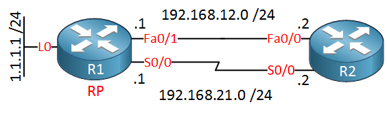
Above, you see two routers, R1 and R2. Between the two routers is a serial link and FastEthernet link, and we will configure R1 as the RP (Rendezvous point). Let’s configure this network:
router ospf 1
 network 0.0.0.0 255.255.255.255 area 0
First, I’ll configure OSPF so that we have full reachability. Now we’ll configure multicast:
R1(config)#ip multicast-routing
R1(config)#interface serial 0/0
R1(config-if)#ip pim sparse-mode

R1(config)#interface loopback 0
R1(config-if)#ip pim sparse-mode

R1(config)#ip pim rp-address 1.1.1.1
We will enable PIM sparse mode, and the loopback 0 interface of R1 will become the RP. Time for R2:
R2(config)#ip multicast-routing
R2(config)#interface serial 0/0
R2(config-if)#ip pim sparse-mode
R2(config)#ip pim rp-address 1.1.1.1
Enable PIM sparse mode and configure the RP…note that I only configured PIM sparse mode on the serial link, not on the FastEthernet link! Let’s verify our work:
R2#show ip route ospf
     1.0.0.0/32 is subnetted, 1 subnets
O       1.1.1.1 [110/11] via 192.168.12.1, 00:03:11, FastEthernet0/0
OSPF has selected the FastEthernet link to reach the loopback0 interface of R1. Let’s also check if PIM is working:
R2#show ip pim neighbor
PIM Neighbor Table
Mode: B - Bidir Capable, DR - Designated Router, N - Default DR Priority,
      S - State Refresh Capable
Neighbor          Interface                Uptime/Expires    Ver   DR
Address                                                            Prio/Mode
192.168.21.1      Serial0/0                00:01:11/00:01:31 v2    1 / S
We have a working PIM neighbor adjacency on the serial link. So far, so good. Let’s see if R2 can join a multicast group…
R2(config)#interface serial 0/0
R2(config-if)#ip igmp join-group 239.1.1.1
We will join the multicast group address 239.1.1.1 on R2. Let’s check the multicast routing table:
R2#show ip mroute 239.1.1.1
IP Multicast Routing Table
Flags: D - Dense, S - Sparse, B - Bidir Group, s - SSM Group, C - Connected,
       L - Local, P - Pruned, R - RP-bit set, F - Register flag,
       T - SPT-bit set, J - Join SPT, M - MSDP created entry,
       X - Proxy Join Timer Running, A - Candidate for MSDP Advertisement,
       U - URD, I - Received Source Specific Host Report,
       Z - Multicast Tunnel, z - MDT-data group sender,
       Y - Joined MDT-data group, y - Sending to MDT-data group
Outgoing interface flags: H - Hardware switched, A - Assert winner
 Timers: Uptime/Expires
 Interface state: Interface, Next-Hop or VCD, State/Mode

(*, 239.1.1.1), 00:01:16/00:01:43, RP 1.1.1.1, flags: SJCL
  Incoming interface: Null, RPF nbr 0.0.0.0
  Outgoing interface list:
    Serial0/0, Forward/Sparse, 00:01:16/00:01:43
Above, you see that R2 tries to join the RP for this multicast group, but if you look closely, you can see that there is no incoming interface and that the RPF neighbor is 0.0.0.0.
The problem is that R2 will do an RPF check on how it can reach the RP. It should be the serial link, but the unicast routing table is telling us something different:
R2#show ip route ospf
     1.0.0.0/32 is subnetted, 1 subnets
O       1.1.1.1 [110/11] via 192.168.12.1, 00:09:26, FastEthernet0/0
If we want to fix this, we need to create a static multicast route to solve the RPF error:
R2(config)#ip mroute 1.1.1.1 255.255.255.255 serial 0/0 I created a static multicast route for the RP, pointing out the serial link. Now take a look again at the multicast routing table:
R2#show ip mroute 239.1.1.1
IP Multicast Routing Table
Flags: D - Dense, S - Sparse, B - Bidir Group, s - SSM Group, C - Connected,
       L - Local, P - Pruned, R - RP-bit set, F - Register flag,
       T - SPT-bit set, J - Join SPT, M - MSDP created entry,
       X - Proxy Join Timer Running, A - Candidate for MSDP Advertisement,
       U - URD, I - Received Source Specific Host Report,
       Z - Multicast Tunnel, z - MDT-data group sender,
       Y - Joined MDT-data group, y - Sending to MDT-data group
Outgoing interface flags: H - Hardware switched, A - Assert winner
 Timers: Uptime/Expires
 Interface state: Interface, Next-Hop or VCD, State/Mode

(*, 239.1.1.1), 00:06:08/stopped, RP 1.1.1.1, flags: SJPCL
  Incoming interface: Serial0/0, RPF nbr 192.168.21.1, Mroute
  Outgoing interface list: Null
Take a good look at this output. Now we see that the incoming interface is the serial0/0 link, and the RPF neighbor is 192.168.21.1 (the IP address on the serial link of R1).
Problem solved. R2 has now successfully joined the RP.
Table of Content
Unit 1. Introduction to Multicast
Unit 2: IGMP (Internet Group Management Protocol)
- Multicast IGMP Version 1
- Multicast IGMP Version 2
- Multicast IGMP Version 3
- Multicast IGMP Filter
- Multicast IGMP Proxy
Unit 3: Multicast L2
- Multicast IGMP Snooping
- IGMP Snooping without Router
- Multicast CGMP (Cisco Group Management Protocol)
Unit 4: Multicast L3
- Multicast Routing
- Multicast PIM Dense Mode
- Multicast PIM Sparse Mode
- Multicast PIM Sparse-Dense Mode
- Multicast PIM Auto RP
- Multicast PIM BSR (Bootstrap)
- RPF (Reverse Path Forwarding)
- Multicast Tunnel RPF Failure
- PIM Designated Router
- PIM Assert
- Multicast PIM Prune Override
- Multicast PIM Register Message
- Anycast RP
- Multicast MSDP SA Filtering
- Multicast Bidirectional PIM
- Multicast Stub Routing and IGMP Helper
- Source Specific Multicast
- Multicast PIM Accept RP
- Multicast PIM Accept Register
- Multicast Auto-RP Mapping agent behind Spoke
- PIM NBMA Mode
- Multicast Boundary Filtering
- Multicast PIM Snooping