Embedded RP IPv6 Multicast
The embedded RP feature that works for IPv6 multicast is a cool trick that embeds the IPv6 address of the RP within the IPv6 multicast group address. By doing this, multicast-enabled routers can extract the RP address just by looking at the multicast group address and using it for a shared tree. The only router where you have to configure the RP address is on the RP itself…that’s it!
There is one problem however…how are we going to fit a 128-bit IPv6 address of the RP within a 128-bit multicast group address? It doesn’t fit! To get around this problem, we have to use some form of compression.
In this lesson, I will show you what the embedded RP address looks like, and how to create one yourself and we will configure a small network to use this feature.
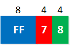
This is what the embedded RP address looks like:

This picture doesn’t tell you much, so let me explain what everything means:
- The first 8 blue bits called “M” define the type of IPv6 address, we are using multicast which means that the first 8 bits have to be set at 1111 1111. In hexadecimal this is “FF”.
- The next 4 red bits, called “F,” are for the flags. When we use the embedded RP feature, we have to set these bits to 0111. In hexadecimal, this is “7”. This is a great identifier when looking at an IPv6 multicast address. When you see the “7” at this position, you know we are dealing with an embedded RP address.
- The four green bits called “S” are the scope. You can use this to define if your multicast traffic should be routed or not, kept within your network, or if it can be used globally. We have some options that we can choose from here:
- Interface-Local scope (1)
- Link-Local scope (2)
- Admin-Local scope (4)
- Site-Local scope (5)
- Organization-Local scope (8)
- Global scope (E)
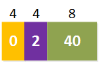
- The 4 yellow bits called “R” are reserved bits. These are always set to 0.
- The 4 purple bits called “I” is the RP interface identifier. We take the last 4 bits of the IPv6 address that we will use as the RP and add those here.
- The 8 olive green bits called “H” is the prefix length in hexadecimal. When you have a prefix length of 64 bits, you will add “40” here. (64 in decimal = 40 in hexadecimal).
- The 64 dark blue bits called “P” is the prefix of the IPv6 address that we use as the RP.
- The last 32 light blue bits called “G” is to define the multicast group address. With 32 bits, this means our first group address will be 0000:0001, and the last group address is FFFF:FFFF.
To understand how to create your own embedded RP address, it’s best to look at an actual example. Let’s imagine we want to use the IPv6 address FC00:2:2:2::2 /64 as our RP. What will the embedded RP address look like? I’ll break it down for you:
- The first 8 bits are FF because we have a multicast address.
- The flags are set to 7 because we use the embedded RP feature.
- The scope is set to organization-local scope. You can pick whatever you like.
- The reserved bits are set to 0. We can’t choose anything else here.
- The RP interface ID is set to 2. These are the last 4 bits of our RP IPv6 address (FC00:2:2:2::2).
- The prefix length is set to 40 since we are using a prefix length of /64. 64 in decimal is 40 in hexadecimal.

- The prefix of our RP IPv6 address is FC00:2:2:2, so we can add it here.
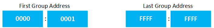
- With 32 bits, there are a lot of group addresses you can use. The first group address starts at 0000:0001, and the last group address is FFFF:FFFF.
The complete embedded RP address will look like this:

I used the first available group address in this example. Are you following me so far? Let’s configure a small network and use the addresses that I just showed you!
Configuration
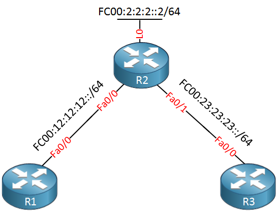
To demonstrate the embedded RP, I will use a small network with three routers. R2 will be the embedded RP using the IPv6 address on its loopback, R1 will join a multicast group address, and R3 will send some traffic to this address. For connectivity, we will use OSPFv3. Here’s what it looks like:
The first thing we should do is enable unicast and multicast routing for IPv6 on all routers:
R1, R2 & R3:
(config)#ipv6 unicast-routing
(config)#ipv6 multicast-routing
Let’s add some IPv6 addresses:
R1(config)#interface fastEthernet 0/0
R1(config-if)#ipv6 address fc00:12:12:12::1/64R2(config)#interface FastEthernet 0/0
R2(config-if)#ipv6 address fc00:12:12:12::2/64
R2(config-if)#interface FastEthernet f0/1
R2(config-if)#ipv6 address fc00:23:23:23::2/64
R2(config)#interface loopback 0
R2(config-if)#ipv6 address fc00:2:2:2::2/64R3(config)#interface FastEthernet 0/0
R3(config-if)#ipv6 address fc00:23:23:23::3/64To make sure R1 and R3 know how to reach the RP, we will add OSPFv3:
R1(config-if)#ipv6 router ospf 1
R1(config-rtr)#router-id 1.1.1.1

R1(config-rtr)#interface FastEthernet 0/0
R1(config-if)#ipv6 ospf 1 area 0R2(config-if)#ipv6 router ospf 1
R2(config-rtr)#router-id 2.2.2.2
R2(config-rtr)#interface FastEthernet 0/0
R2(config-if)#ipv6 ospf 1 area 0
R2(config-rtr)#interface FastEthernet 0/1
R2(config-if)#ipv6 ospf 1 area 0
R2(config-rtr)#interface Loopback 0
R2(config-if)#ipv6 ospf 1 area 0R3(config-if)#ipv6 router ospf 1
R3(config-rtr)#router-id 3.3.3.3
R3(config-rtr)#interface FastEthernet 0/0
R3(config-if)#ipv6 ospf 1 area 0Now we will configure R2 as the RP. This is the only router where you have to configure this:
R2(config)#ipv6 pim rp-address fc00:2:2:2::2Let’s configure R1 to join a multicast group address that has FC00:2:2:2::2 as the embedded RP:
R1(config)#interface FastEthernet 0/0
R1(config-if)#ipv6 mld join-group FF78:0240:FC00:2:2:2:0:1
That’s all we have to configure to get this show on the road. Let’s verify our work!
Verification
R1 has joined a multicast group address, so let’s see what R2 thinks of that:
R2#show ipv6 mroute
Multicast Routing Table
Flags: D - Dense, S - Sparse, B - Bidir Group, s - SSM Group,
       C - Connected, L - Local, I - Received Source Specific Host Report,
       P - Pruned, R - RP-bit set, F - Register flag, T - SPT-bit set,
       J - Join SPT
Timers: Uptime/Expires
Interface state: Interface, State

(*, FF78:240:FC00:2:2:2:0:1), 00:05:23/never, RP FC00:2:2:2::2, flags: SCJ
  Incoming interface: Tunnel2
  RPF nbr: FC00:2:2:2::2
  Immediate Outgoing interface list:
    FastEthernet0/0, Forward, 00:05:23/never
It looks promising, R2 has an entry for the multicast group address, and it shows its loopback address as the RP. It seems R1 figured out how to reach the RP…let’s try a ping from R3:
R3#ping FF78:240:FC00:2:2:2:0:1
Output Interface: FastEthernet0/0
Type escape sequence to abort.
Sending 5, 100-byte ICMP Echos to FF78:240:FC00:2:2:2:0:1, timeout is 2 seconds:
Packet sent with a source address of FC00:23:23:23::3

Reply to request 0 received from FC00:12:12:12::1, 32 ms
Reply to request 1 received from FC00:12:12:12::1, 36 ms
Reply to request 2 received from FC00:12:12:12::1, 28 ms
Reply to request 3 received from FC00:12:12:12::1, 36 ms
Reply to request 4 received from FC00:12:12:12::1, 36 ms
Success rate is 100 percent (5/5), round-trip min/avg/max = 28/33/36 ms
5 multicast replies and 0 errors.
Great! our ping from R3 is getting a response from R1. Let’s take one more look at the multicast routing table of R2:
R2#show ipv6 mroute
Multicast Routing Table
Flags: D - Dense, S - Sparse, B - Bidir Group, s - SSM Group,
       C - Connected, L - Local, I - Received Source Specific Host Report,
       P - Pruned, R - RP-bit set, F - Register flag, T - SPT-bit set,
       J - Join SPT
Timers: Uptime/Expires
Interface state: Interface, State

(*, FF78:240:FC00:2:2:2:0:1), 00:07:51/never, RP FC00:2:2:2::2, flags: SCJ
  Incoming interface: Tunnel2
  RPF nbr: FC00:2:2:2::2
  Immediate Outgoing interface list:
    FastEthernet0/0, Forward, 00:07:51/never

(FC00:23:23:23::3, FF78:240:FC00:2:2:2:0:1), 00:00:37/00:02:52, flags: SJT
  Incoming interface: FastEthernet0/1
  RPF nbr: FE80::C002:29FF:FEE2:0
  Inherited Outgoing interface list:
    FastEthernet0/0, Forward, 00:07:51/never
Table of Content
Unit 1. Introduction to Multicast
Unit 2: IGMP (Internet Group Management Protocol)
- Multicast IGMP Version 1
- Multicast IGMP Version 2
- Multicast IGMP Version 3
- Multicast IGMP Filter
- Multicast IGMP Proxy
Unit 3: Multicast L2
- Multicast IGMP Snooping
- IGMP Snooping without Router
- Multicast CGMP (Cisco Group Management Protocol)
Unit 4: Multicast L3
- Multicast Routing
- Multicast PIM Dense Mode
- Multicast PIM Sparse Mode
- Multicast PIM Sparse-Dense Mode
- Multicast PIM Auto RP
- Multicast PIM BSR (Bootstrap)
- RPF (Reverse Path Forwarding)
- Multicast Tunnel RPF Failure
- PIM Designated Router
- PIM Assert
- Multicast PIM Prune Override
- Multicast PIM Register Message
- Anycast RP
- Multicast MSDP SA Filtering
- Multicast Bidirectional PIM
- Multicast Stub Routing and IGMP Helper
- Source Specific Multicast
- Multicast PIM Accept RP
- Multicast PIM Accept Register
- Multicast Auto-RP Mapping agent behind Spoke
- PIM NBMA Mode
- Multicast Boundary Filtering
- Multicast PIM Snooping