Multicast Anycast RP Configuration
There are a number of methods to create redundancy for our RPs (Rendezvous Points) in our multicast topology. Using AutoRP or Bootstrap we can configure multiple routers to advertise themselves as RPs (Rendezvous Points) so that when one router fails, another one can take over. Anycast RP is a different method to create redundancy…
The idea behind anycast RP is that we configure a single IP address on multiple routers and advertise it in our IGP. When you have multiple RPs with the same IP address, it means that our sources and receivers will always be routed to the closest RP based on the unicast routing table. PIM Join messages from receivers might be sent to one RP, while PIM-designated routers register their local sources to another RP.
To make sure that all Rendezvous points know about all the different sources out there, we will use MSDP (Multicast Source Discovery Protocol). Normally MSDP is used to allow multicast routing between different autonomous systems but it’s also a great companion for anycast RP.
Configuration
Let’s look at an example of how we can configure anycast RP. This is the topology that I will use:
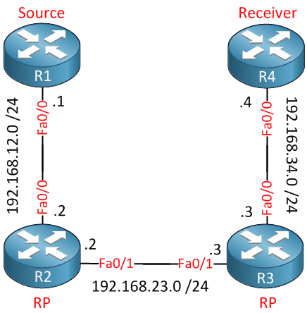
In this scenario, R1 will be the source, and R4 will be the receiver for a multicast stream. R2 and R3 will be our Rendezvous points. Before we get to the interesting stuff, we’ll have to do our homework. I will enable OSPF on all interfaces so that our routing tables are filled:
R1,R2,R3 & R4:
(config)#router ospf 1
(config-router)#network 0.0.0.0 255.255.255.255 area 0
Don’t forget to enable multicast routing on R2 and R3 because they’ll have to forward the multicast packets:
R2 & R3:
(config)#ip multicast-routing
And make sure to enable PIM on the interfaces facing the source (R1), the receiver (R4), and between R2/R3:
R2(config)#interface fastEthernet 0/0
R2(config-if)#ip pim sparse-mode
R2(config-if)#exit
R2(config)#interface fastEthernet 0/1
R2(config-if)#ip pim sparse-modeR3(config)#interface fastEthernet 0/0
R3(config-if)#ip pim sparse-mode
R3(config-if)#exit
R3(config)#interface fastEthernet 0/1
R3(config-if)#ip pim sparse-mode Now we get to the interesting part. We’ll create a new loopback interface on R2 and R3 where we configure the same IP address as the Rendezvous Point:
R2 & R3:
(config)#interface loopback 0
(config-if)#ip address 23.23.23.23 255.255.255.255
Make sure you advertise this address in your IGP. Because I used the network 0.0.0.0 255.255.255.255 command for OSPF, it will be automatically advertised. All routers that need to forward multicast traffic will have to know where the RP is. You can use AutoRP, Bootstrap, or static addresses for this. To keep things simple, I’ll use the static method:
R2 & R3:
(config)#ip pim rp-address 23.23.23.23
Now we will configure R4 to join a multicast group address (I’ll pick 239.1.1.1), and we’ll take a look at which RP it will join:
R4(config)#interface fastEthernet 0/0
R4(config-if)#ip igmp join-group 239.1.1.1
Of course R3 will be the closest RP for R4 so you’ll find a (*,G) entry for 239.1.1.1:
R3#show ip mroute 239.1.1.1
IP Multicast Routing Table
Flags: D - Dense, S - Sparse, B - Bidir Group, s - SSM Group, C - Connected,
       L - Local, P - Pruned, R - RP-bit set, F - Register flag,
       T - SPT-bit set, J - Join SPT, M - MSDP created entry,
       X - Proxy Join Timer Running, A - Candidate for MSDP Advertisement,
       U - URD, I - Received Source Specific Host Report,
       Z - Multicast Tunnel, z - MDT-data group sender,
       Y - Joined MDT-data group, y - Sending to MDT-data group
Outgoing interface flags: H - Hardware switched, A - Assert winner
 Timers: Uptime/Expires
 Interface state: Interface, Next-Hop or VCD, State/Mode

(*, 239.1.1.1), 00:06:35/00:02:08, RP 23.23.23.23, flags: SJC
  Incoming interface: Null, RPF nbr 0.0.0.0
  Outgoing interface list:
    FastEthernet0/1, Forward/Sparse, 00:06:35/00:02:08
Right now, nobody is sending anything to this multicast group address. Let’s send some pings from R1 to 239.1.1.1 to get the packets flowing…
R1#ping 239.1.1.1 repeat 5

Type escape sequence to abort.
Sending 5, 100-byte ICMP Echos to 239.1.1.1, timeout is 2 seconds:
.....
None of our multicast packets make it to the receiver…any idea why? Let’s look at the multicast routing table on R2:
R2#show ip mroute 239.1.1.1
IP Multicast Routing Table
Flags: D - Dense, S - Sparse, B - Bidir Group, s - SSM Group, C - Connected,
       L - Local, P - Pruned, R - RP-bit set, F - Register flag,
       T - SPT-bit set, J - Join SPT, M - MSDP created entry,
       X - Proxy Join Timer Running, A - Candidate for MSDP Advertisement,
       U - URD, I - Received Source Specific Host Report,
       Z - Multicast Tunnel, z - MDT-data group sender,
       Y - Joined MDT-data group, y - Sending to MDT-data group
Outgoing interface flags: H - Hardware switched, A - Assert winner
 Timers: Uptime/Expires
 Interface state: Interface, Next-Hop or VCD, State/Mode

(*, 239.1.1.1), 00:01:17/stopped, RP 23.23.23.23, flags: SP
  Incoming interface: Null, RPF nbr 0.0.0.0
  Outgoing interface list: Null

(192.168.12.1, 239.1.1.1), 00:00:51/00:02:50, flags: PT
  Incoming interface: FastEthernet0/0, RPF nbr 0.0.0.0
  Outgoing interface list: Null
R2 is the closest RP for R1, and you can see the (192.168.12.1, 239.1.1.1) entry. There are no outgoing interfaces, however…what about R3, our second RP?
R3#show ip mroute 239.1.1.1
IP Multicast Routing Table
Flags: D - Dense, S - Sparse, B - Bidir Group, s - SSM Group, C - Connected,
       L - Local, P - Pruned, R - RP-bit set, F - Register flag,
       T - SPT-bit set, J - Join SPT, M - MSDP created entry,
       X - Proxy Join Timer Running, A - Candidate for MSDP Advertisement,
       U - URD, I - Received Source Specific Host Report,
       Z - Multicast Tunnel, z - MDT-data group sender,
       Y - Joined MDT-data group, y - Sending to MDT-data group
Outgoing interface flags: H - Hardware switched, A - Assert winner
 Timers: Uptime/Expires
 Interface state: Interface, Next-Hop or VCD, State/Mode

(*, 239.1.1.1), 00:07:28/00:02:12, RP 23.23.23.23, flags: SJC
  Incoming interface: Null, RPF nbr 0.0.0.0
  Outgoing interface list:
    FastEthernet0/1, Forward/Sparse, 00:07:28/00:02:12
Nothing has changed on R3. We still see the outgoing interface, but there is no incoming traffic! The problem is that our source has joined one RP (R2), and the receiver has joined another RP (R3). The two Rendezvous Points are not sharing any information, so we are stuck here. In order to solve this, R3 somehow needs to learn from R2 that there is an active source. This is exactly what MSDP will do for us!
To configure MSDP between the two RPs, we’ll use two new loopback interfaces with unique IP addresses. It will look like this:
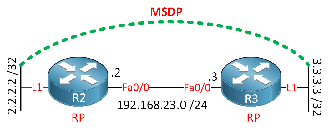
Let’s create the loopback interfaces and configure MSDP:
R2(config)#interface loopback1
R2(config-if)#ip address 2.2.2.2 255.255.255.255
R3(config-if)#exit
R2(config)#ip msdp originator-id Loopback 1
R2(config)#ip msdp peer 3.3.3.3 connect-source Loopback 1R3(config)#interface loopback1
R3(config-if)#ip address 3.3.3.3 255.255.255.255
R3(config-if)#exit
R3(config)#ip msdp originator-id Loopback 1
R3(config)#ip msdp peer 2.2.2.2 connect-source Loopback 1The ip msdp originator-id command is used to tell MSDP what IP address to use as an “ID,” which is similar to the OSPF or BGP router ID. By default, the router will select the highest IP address on the router, which means that R2 and R3 both would have selected 23.23.23.23. If I don’t use this command then MSDP will be unable to form a peering between R2 and R3.
The ip msdp peer command is used to configure your MSDP peer. Make sure to use the loopback interface as the source.
Verification
After a few seconds, you will see the following on your console:
R2#
%MSDP-5-PEER_UPDOWN: Session to peer 3.3.3.3 going up
R3#
%MSDP-5-PEER_UPDOWN: Session to peer 2.2.2.2 going upMSDP appears to be alive. You can also use the following command to verify this:
R2#show ip msdp peer
MSDP Peer 3.3.3.3 (?), AS ?
  Connection status:
    State: Up, Resets: 0, Connection source: Loopback1 (2.2.2.2)
    Uptime(Downtime): 00:01:36, Messages sent/received: 2/2
    Output messages discarded: 0
    Connection and counters cleared 00:03:06 ago
  SA Filtering:
    Input (S,G) filter: none, route-map: none
    Input RP filter: none, route-map: none
    Output (S,G) filter: none, route-map: none
    Output RP filter: none, route-map: none
  SA-Requests:
    Input filter: none
  Peer ttl threshold: 0
  SAs learned from this peer: 0
  Input queue size: 0, Output queue size: 0
MD5 signature protection on MSDP TCP connection: not enabledR3#show ip msdp peer 2.2.2.2
MSDP Peer 2.2.2.2 (?), AS ?
Connection status:
State: Up, Resets: 0, Connection source: Loopback1 (3.3.3.3)
Uptime(Downtime): 00:01:49, Messages sent/received: 2/2
Output messages discarded: 0
Connection and counters cleared 00:02:41 ago
SA Filtering:
Input (S,G) filter: none, route-map: none
Input RP filter: none, route-map: none
Output (S,G) filter: none, route-map: none
Output RP filter: none, route-map: none
SA-Requests:
Input filter: none
Peer ttl threshold: 0
SAs learned from this peer: 0
Input queue size: 0, Output queue size: 0
MD5 signature protection on MSDP TCP connection: not enabledNow before we start another ping from R1 to see some MSDP magic, I’ll activate a debug so you can see what MSDP does ‘behind the scenes’ :
R3#:
debug ip msdp detail
MSDP Detail debugging is on
Now let’s start that ping from R1 again:
R1#ping 239.1.1.1 repeat 5

Type escape sequence to abort.
Sending 5, 100-byte ICMP Echos to 239.1.1.1, timeout is 2 seconds:

Reply to request 0 from 192.168.34.4, 12 ms
Reply to request 1 from 192.168.34.4, 12 ms
Reply to request 2 from 192.168.34.4, 12 ms
Reply to request 3 from 192.168.34.4, 8 ms
Reply to request 4 from 192.168.34.4, 12 ms
Great! it’s working…but why? Take a look at the debug on R3:
R3#
MSDP(0): WAVL Insert SA Source 192.168.12.1 Group 239.1.1.1 RP 2.2.2.2 Successful
MSDP(0): Forward decapsulated SA data for (192.168.12.1, 239.1.1.1) on FastEthernet0/1
R3 has learned about a new active source because of a SA (Source-Active) MSDP message from R2. It will use this information to fill its multicast routing table. You can use the following command to see what sources MSDP has learned:
R3#show ip msdp sa-cache
MSDP Source-Active Cache - 1 entries
(192.168.12.1, 239.1.1.1), RP 2.2.2.2, AS ?,00:03:01/00:05:29, Peer 2.2.2.2
What do our multicast routing tables look like now? Let’s take a look:
R2#show ip mroute 239.1.1.1
IP Multicast Routing Table
Flags: D - Dense, S - Sparse, B - Bidir Group, s - SSM Group, C - Connected,
       L - Local, P - Pruned, R - RP-bit set, F - Register flag,
       T - SPT-bit set, J - Join SPT, M - MSDP created entry,
       X - Proxy Join Timer Running, A - Candidate for MSDP Advertisement,
       U - URD, I - Received Source Specific Host Report,
       Z - Multicast Tunnel, z - MDT-data group sender,
       Y - Joined MDT-data group, y - Sending to MDT-data group
Outgoing interface flags: H - Hardware switched, A - Assert winner
 Timers: Uptime/Expires
 Interface state: Interface, Next-Hop or VCD, State/Mode

(*, 239.1.1.1), 00:12:40/stopped, RP 23.23.23.23, flags: SP
  Incoming interface: Null, RPF nbr 0.0.0.0
  Outgoing interface list: Null

(192.168.12.1, 239.1.1.1), 00:03:31/00:03:27, flags: TA
  Incoming interface: FastEthernet0/0, RPF nbr 0.0.0.0
  Outgoing interface list:
    FastEthernet0/1, Forward/Sparse, 00:03:31/00:02:57
R2 has added the interface toward R3 in its outgoing interface list. What about R3?
R3#show ip mroute 239.1.1.1
IP Multicast Routing Table
Flags: D - Dense, S - Sparse, B - Bidir Group, s - SSM Group, C - Connected,
       L - Local, P - Pruned, R - RP-bit set, F - Register flag,
       T - SPT-bit set, J - Join SPT, M - MSDP created entry,
       X - Proxy Join Timer Running, A - Candidate for MSDP Advertisement,
       U - URD, I - Received Source Specific Host Report,
       Z - Multicast Tunnel, z - MDT-data group sender,
       Y - Joined MDT-data group, y - Sending to MDT-data group
Outgoing interface flags: H - Hardware switched, A - Assert winner
 Timers: Uptime/Expires
 Interface state: Interface, Next-Hop or VCD, State/Mode

(*, 239.1.1.1), 00:18:28/stopped, RP 23.23.23.23, flags: SJC
  Incoming interface: Null, RPF nbr 0.0.0.0
  Outgoing interface list:
    FastEthernet0/1, Forward/Sparse, 00:18:28/00:02:11

(192.168.12.1, 239.1.1.1), 00:03:52/00:02:51, flags: MT
  Incoming interface: FastEthernet0/1, RPF nbr 192.168.23.2
  Outgoing interface list:
    FastEthernet0/0, Forward/Sparse, 00:03:52/00:02:11
Table of Content
Unit 1. Introduction to Multicast
Unit 2: IGMP (Internet Group Management Protocol)
- Multicast IGMP Version 1
- Multicast IGMP Version 2
- Multicast IGMP Version 3
- Multicast IGMP Filter
- Multicast IGMP Proxy
Unit 3: Multicast L2
- Multicast IGMP Snooping
- IGMP Snooping without Router
- Multicast CGMP (Cisco Group Management Protocol)
Unit 4: Multicast L3
- Multicast Routing
- Multicast PIM Dense Mode
- Multicast PIM Sparse Mode
- Multicast PIM Sparse-Dense Mode
- Multicast PIM Auto RP
- Multicast PIM BSR (Bootstrap)
- RPF (Reverse Path Forwarding)
- Multicast Tunnel RPF Failure
- PIM Designated Router
- PIM Assert
- Multicast PIM Prune Override
- Multicast PIM Register Message
- Anycast RP
- Multicast MSDP SA Filtering
- Multicast Bidirectional PIM
- Multicast Stub Routing and IGMP Helper
- Source Specific Multicast
- Multicast PIM Accept RP
- Multicast PIM Accept Register
- Multicast Auto-RP Mapping agent behind Spoke
- PIM NBMA Mode
- Multicast Boundary Filtering
- Multicast PIM Snooping