EIGRP Loop-Free Alternate (LFA) Fast Reroute (FRR)
EIGRP Loop-Free Alternate (LFA) Fast Reroute (FRR) is a feature that allows EIGRP to switch to a backup path in less than 50 ms. Fast reroute means we switch to another next hop, Loop-free alternate is an alternative path in the network that is loop free.
Now you might be thinking that this sounds familiar. After all, EIGRP has feasible successors. Those are loop-free alternate paths that EIGRP has calculated. If the successor fails, EIGRP can use a feasible successor right away.
This is true, but there’s one big “gotcha”. EIGRP feasible successors are not installed in the routing table right away. Only the successor route is installed. When the successor fails, EIGRP installs the feasible successor, and this takes time. Fast reroute installs both the successor route and the feasible successor route in the routing table which makes convergence even faster.
IGPs can calculate LFAs using different methods:
- Per-link: all prefixes that are reachable through a certain link share the same information, they all use the same next hop address. When we calculate the LFA per link, we calculate a single backup next hop address for all prefixes that use the link. This means that if the primary link fails, all prefixes are switched to a secondary link. The advantage of per-link LFAs is that it’s simple to calculate, it uses less CPU and memory resources. The disadvantage, however, is that once the primary link fails, all traffic to the prefixes that used the primary link are suddenly switched to a single backup link. It is possible that your backup link gets overburdened with this sudden spike of traffic.
- Per-prefix: we calculate an LFA for each prefix, in other words for each possible destination. This requires more resources, but it does offer better load balancing. It’s possible that two prefixes currently use the same path, but once the primary link fails, they use different backup next hops. This spreads your traffic more throughout the network.
When you have multiple possible LFAs, fast reroute has to select one LFA. EIGRP will not just select the “best” (lowest metric) feasible successor but uses some “tie-breakers” to select the best LFA. When you use per-prefix LFA, we have these four attributes:
- Interface disjoint: don’t select an LFA that uses the same outgoing interface as the primary path. Imagine we have R1, connected to R2 and R3 on a multi-access segment. R1 also has a connection to R4 using a different interface. R2, R3, and R4 all offer a path to a certain destination. R2 is the successor, R3 and R4 are feasible successors. R3 has a better metric. Which feasible successor would you prefer? R1 can reach R2 and R3 using the same interface, R4 through a different interface. There is a risk that once R2 is unreachable that R3 also becomes unreachable (maybe the switch fails). It might be a better idea to prefer R4 instead…I’m going to show you this in an example, later in this lesson.
- Line card disjoint: don’t select an LFA that shares a line card with the primary card. The same logic as the interface-disjoint applies here. There is a risk that your line card fails which means that both the successor and feasible successor are unusable.
- Lowest repair path metric: don’t select an LFA with a high metric. This ensures that only the lowest metric LFAs remain.
- Shared Risk Link Group (SRLG): don’t select LFAs that use the same SRLG. This one requires some more explanation. Imagine we have R1, connected to R2, R3, and R4. R2 and R3 use the same uplink to reach a certain destination. R4 uses a different link to reach the same destination. R2 is the successor, R3 and R4 are feasible successors, but R3 has a better metric. Which feasible successor would you prefer? R3 has a lower metric, but it uses the same uplink…that’s a risk. By adding R2 and R3 to the same SRLG, you can tell EIGRP to prefer R4 since it uses a different uplink. I will show you an example of SRLG on some routers later in this lesson.
You now know the basics of Fast reroute and Loop free alternate. Let’s look at it in action, shall we…
Configuration
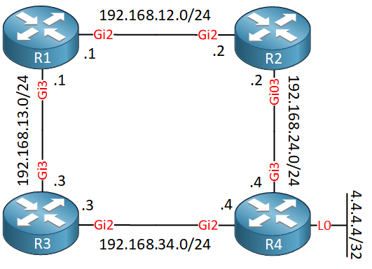
Here is the first topology I use to demonstrate the basics of fast reroute:

These four routers run EIGRP; there’s a loopback on R4 with network 4.4.4.4/32. R1 can go through R2 or R3 to get there. The delay on R1’s GigabitEthernet3 interface has been increased so that R2 is our successor and R3 our feasible successor.
- Configurations
- R1
- R2
- R3
- R4
Want to take a look for yourself? Here you will find the startup configuration of each device.
Let’s take a look at the EIGRP topology table of R1:
R1#show ip eigrp topology 4.4.4.4/32
EIGRP-IPv4 VR(FRR) Topology Entry for AS(1)/ID(192.168.12.1) for 4.4.4.4/32
  State is Passive, Query origin flag is 1, 1 Successor(s), FD is 2048000, RIB is 16000
  Descriptor Blocks:
  192.168.12.2 (GigabitEthernet2), from 192.168.12.2, Send flag is 0x0
      Composite metric is (2048000/1392640), route is Internal
      Vector metric:
        Minimum bandwidth is 1000000 Kbit
        Total delay is 21250000 picoseconds
        Reliability is 255/255
        Load is 1/255
        Minimum MTU is 1500
        Hop count is 2
        Originating router is 4.4.4.4
  192.168.13.3 (GigabitEthernet3), from 192.168.13.3, Send flag is 0x0
      Composite metric is (2703360/1392640), route is Internal
      Vector metric:
        Minimum bandwidth is 1000000 Kbit
        Total delay is 31250000 picoseconds
        Reliability is 255/255
        Load is 1/255
        Minimum MTU is 1500
        Hop count is 2
        Originating router is 4.4.4.4
The output above confirms that R2 is our successor and R3 our feasible successor. Let’s take a look at the routing table:
R1#show ip route 4.4.4.4
Routing entry for 4.4.4.4/32
  Known via "eigrp 1", distance 90, metric 16000, type internal
  Redistributing via eigrp 1
  Last update from 192.168.12.2 on GigabitEthernet2, 00:07:45 ago
  Routing Descriptor Blocks:
  * 192.168.12.2, from 192.168.12.2, 00:07:45 ago, via GigabitEthernet2
      Route metric is 16000, traffic share count is 1
      Total delay is 21 microseconds, minimum bandwidth is 1000000 Kbit
      Reliability 255/255, minimum MTU 1500 bytes
      Loading 1/255, Hops 2
As expected, we only see the successor route in the routing table. Let’s look at the CEF table:
R1#show ip cef 4.4.4.4
4.4.4.4/32
  nexthop 192.168.12.2 GigabitEthernet2
We only see the successor there as well. Now let’s configure fast reroute on R1. I’m using CSR1000v routers that support per-prefix LFA:
R1(config)#router eigrp FRR
R1(config-router)#address-family ipv4 unicast autonomous-system 1
R1(config-router-af)#topology base
R1(config-router-af-topology)#fast-reroute per-prefix all
Let’s take another look at the routing table:
R1#show ip route 4.4.4.4
Routing entry for 4.4.4.4/32
  Known via "eigrp 1", distance 90, metric 16000, type internal
  Redistributing via eigrp 1
  Last update from 192.168.12.2 on GigabitEthernet2, 00:01:11 ago
  Routing Descriptor Blocks:
  * 192.168.12.2, from 192.168.12.2, 00:01:11 ago, via GigabitEthernet2
      Route metric is 16000, traffic share count is 1
      Total delay is 21 microseconds, minimum bandwidth is 1000000 Kbit
      Reliability 255/255, minimum MTU 1500 bytes
      Loading 1/255, Hops 0
      Repair Path: 192.168.13.3, via GigabitEthernet3
The output above is interesting. We still see the successor route, but at the bottom, you can see the repair path…that’s our feasible successor. We can also find this in the CEF table:
R1#show ip cef 4.4.4.4
4.4.4.4/32
  nexthop 192.168.12.2 GigabitEthernet2
    repair: attached-nexthop 192.168.13.3 GigabitEthernet3
The feasible successor is already in the forwarding table, saving valuable time when the successor route fails.
Tie Breakers
Let’s also take a look at some examples to help you understand the tie breakers. In the previous example, we only had one feasible successor, so there’s not much to choose. What if we have two or more feasible successors?
Interface Disjoint
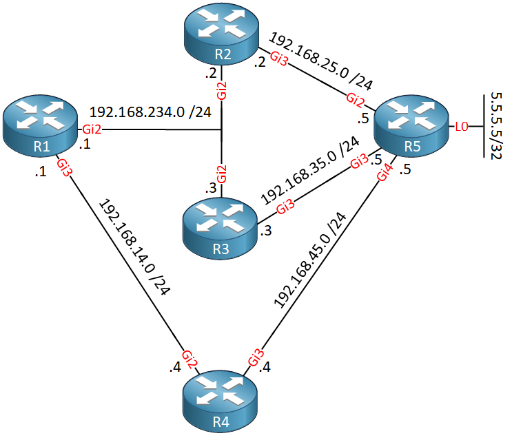
Let’s take a closer look at the interface disjoint tie breaker. I use the following topology to demonstrate this:

Above we have five routers, running EIGRP. Behind R5 we have a loopback interface with network 5.5.5.5/32. R1 can use R2, R3, and R4 to reach it. I used an offset-list on R3 and R4 so that R2 is the successor, R3 and R4 two feasible successors where R3 has a slightly better metric.
- Configurations
- R1
- R2
- R3
- R4
- R5
Want to take a look for yourself? Here you will find the startup configuration of each device.
Let’s take a look at the routing table of R1:
R1#show ip route 5.5.5.5
Routing entry for 5.5.5.5/32
  Known via "eigrp 1", distance 90, metric 16000, type internal
  Redistributing via eigrp 1
  Last update from 192.168.123.2 on GigabitEthernet2, 00:01:43 ago
  Routing Descriptor Blocks:
  * 192.168.123.2, from 192.168.123.2, 00:01:43 ago, via GigabitEthernet2
      Route metric is 16000, traffic share count is 1
      Total delay is 21 microseconds, minimum bandwidth is 1000000 Kbit
      Reliability 255/255, minimum MTU 1500 bytes
      Loading 1/255, Hops 0
Above we see that R1 uses R2 as the successor to reach 5.5.5.5/32. Let’s check the EIGRP topology table:
R1#show ip eigrp topology 5.5.5.5/32
EIGRP-IPv4 VR(FRR) Topology Entry for AS(1)/ID(192.168.123.1) for 5.5.5.5/32
  State is Passive, Query origin flag is 1, 1 Successor(s), FD is 2048000, RIB is 16000
  Descriptor Blocks:
  192.168.123.2 (GigabitEthernet2), from 192.168.123.2, Send flag is 0x0
      Composite metric is (2048000/1392640), route is Internal
      Vector metric:
        Minimum bandwidth is 1000000 Kbit
        Total delay is 21250000 picoseconds
        Reliability is 255/255
        Load is 1/255
        Minimum MTU is 1500
        Hop count is 2
        Originating router is 192.168.35.5
  192.168.14.4 (GigabitEthernet3), from 192.168.14.4, Send flag is 0x0
      Composite metric is (2050000/1394640), route is Internal
      Vector metric:
        Minimum bandwidth is 1000000 Kbit
        Total delay is 21280518 picoseconds
        Reliability is 255/255
        Load is 1/255
        Minimum MTU is 1500
        Hop count is 2
        Originating router is 192.168.35.5
  192.168.123.3 (GigabitEthernet2), from 192.168.123.3, Send flag is 0x0
      Composite metric is (2049000/1393640), route is Internal
      Vector metric:
        Minimum bandwidth is 1000000 Kbit
        Total delay is 21265259 picoseconds
        Reliability is 255/255
        Load is 1/255
        Minimum MTU is 1500
        Hop count is 2
        Originating router is 192.168.35.5
In the topology table, we see that R2 is the successor, R3 and R4 are feasible successors, and R3 has a slightly better metric (2049000) than R4 (2050000). Here’s the CEF forwarding table:
R1#show ip cef 5.5.5.5/32
5.5.5.5/32
  nexthop 192.168.123.2 GigabitEthernet2
Right now, only the successor route is installed. Let’s enable fast reroute:
R1(config)#router eigrp FRR
R1(config-router)#address-family ipv4 unicast autonomous-system 1
R1(config-router-af)#topology base
R1(config-router-af-topology)#fast-reroute per-prefix all
Let’s have another look at the CEF forwarding table:
R1#show ip cef 5.5.5.5/32
5.5.5.5/32
  nexthop 192.168.123.2 GigabitEthernet2
    repair: attached-nexthop 192.168.14.4 GigabitEthernet3
We now see an additional entry… R4 is the backup path. Why? R3 had a better metric after all. This is because of our LFA tie-breakers:
R1#show running-config all | include tie-break
   fast-reroute tie-break linecard-disjoint 40
   fast-reroute tie-break lowest-backup-path-metric 30
   fast-reroute tie-break interface-disjoint 20
   fast-reroute tie-break srlg-disjoint 10
The lower the priority, the better. I’m using a virtual CSR1000V router, so there are no line cards to look for. R2 and R3 use the same outgoing interface (GigabitEthernet2), so that’s why we don’t prefer R3 as an LFA and R4 is selected.
SRLG disjoint
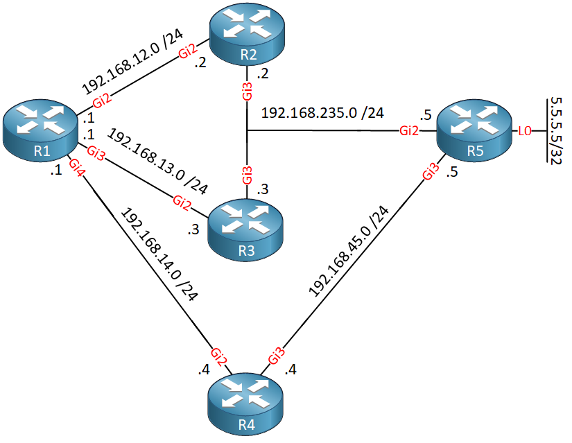
Let’s look at another tie breaker, the SRLG (Shared Risk Link Group) disjoint. I need another topology to demonstrate this:

We have the same number of routers, and 5.5.5.5/32 is behind R5. R2, R3, and R5 are now connected to the same multi-access segment. I used an offset-list on R3 and R4 so that R2 becomes the successor and R3/R4 feasible successors. R3 has a better metric than R4.
- Configurations
- R1
- R2
- R3
- R4
- R5
Want to take a look for yourself? Here you will find the startup configuration of each device.
Let’s check the routing table of R1:
R1#show ip route 5.5.5.5
Routing entry for 5.5.5.5/32
  Known via "eigrp 1", distance 90, metric 16000, type internal
  Redistributing via eigrp 1
  Last update from 192.168.12.2 on GigabitEthernet2, 00:03:12 ago
  Routing Descriptor Blocks:
  * 192.168.12.2, from 192.168.12.2, 00:03:12 ago, via GigabitEthernet2
      Route metric is 16000, traffic share count is 1
      Total delay is 21 microseconds, minimum bandwidth is 1000000 Kbit
      Reliability 255/255, minimum MTU 1500 bytes
      Loading 1/255, Hops 2
R2 is our successor, here’s the EIGRP topology table:
R1#show ip eigrp topology 5.5.5.5/32
EIGRP-IPv4 VR(FRR) Topology Entry for AS(1)/ID(192.168.12.1) for 5.5.5.5/32
  State is Passive, Query origin flag is 1, 1 Successor(s), FD is 2048000, RIB is 16000
  Descriptor Blocks:
  192.168.12.2 (GigabitEthernet2), from 192.168.12.2, Send flag is 0x0
      Composite metric is (2048000/1392640), route is Internal
      Vector metric:
        Minimum bandwidth is 1000000 Kbit
        Total delay is 21250000 picoseconds
        Reliability is 255/255
        Load is 1/255
        Minimum MTU is 1500
        Hop count is 2
        Originating router is 5.5.5.5
  192.168.13.3 (GigabitEthernet3), from 192.168.13.3, Send flag is 0x0
      Composite metric is (2049000/1393640), route is Internal
      Vector metric:
        Minimum bandwidth is 1000000 Kbit
        Total delay is 21265259 picoseconds
        Reliability is 255/255
        Load is 1/255
        Minimum MTU is 1500
        Hop count is 2
        Originating router is 5.5.5.5
  192.168.14.4 (GigabitEthernet4), from 192.168.14.4, Send flag is 0x0
      Composite metric is (2050000/1394640), route is Internal
      Vector metric:
        Minimum bandwidth is 1000000 Kbit
        Total delay is 21280518 picoseconds
        Reliability is 255/255
        Load is 1/255
        Minimum MTU is 1500
        Hop count is 2
        Originating router is 5.5.5.5
We can confirm that R2 is the successor, R3 and R4 are feasible successors. R3 has a lower metric than R4. Here’s the CEF forwarding table:
R1#show ip cef 5.5.5.5/32
5.5.5.5/32
  nexthop 192.168.12.2 GigabitEthernet2
So far so good, let’s enable fast reroute:
R1(config)#router eigrp FRR
R1(config-router)#address-family ipv4 unicast autonomous-system 1
R1(config-router-af)#topology base
R1(config-router-af-topology)#fast-reroute per-prefix all
Here’s the CEF forwarding table again:
R1#show ip cef 5.5.5.5/32
5.5.5.5/32
  nexthop 192.168.12.2 GigabitEthernet2
    repair: attached-nexthop 192.168.13.3 GigabitEthernet3
R1 uses R3 as the backup next hop. Is this a good idea? After all, R2 and R3 use the same multi-access segment to reach R5. It’s likely that when R2 is unable to reach R5 that R3 has the same issue…
To change this, we can assign SRLG ids to the interfaces of R1. This way, we can tell R1 that R2 and R3 should be treated similarly:
R1(config)#interface GigabitEthernet 2
R1(config-if)#srlg gid 23
R1(config)#interface GigabitEthernet 3
R1(config-if)#srlg gid 23
R1(config)#interface GigabitEthernet 4
R1(config-if)#srlg gid 4
The interfaces that connect to R2 and R3 now belong to SRLG group ID 23. I assigned another ID (4) to the interface that connects to R4. Let’s take another look at the CEF table:
R1#show ip cef 5.5.5.5/32
5.5.5.5/32
  nexthop 192.168.12.2 GigabitEthernet2
    repair: attached-nexthop 192.168.14.4 GigabitEthernet4
R1 now uses R4 as the backup path. Why? Let’s take another look at the tie breakers:
R1#show running-config all | include tie-break
   fast-reroute tie-break linecard-disjoint 40
   fast-reroute tie-break lowest-backup-path-metric 30
   fast-reroute tie-break interface-disjoint 20
   fast-reroute tie-break srlg-disjoint 10
The SRLG disjoint tie-breaker has the lowest priority of them all. Fast reroute won’t select LFAs that belong to the same SRLG group ID as the primary path.
Conclusion
You have now learned:
- How EIGRP uses Fast Reroute (FRR) to find LFAs (Loop Free Alternatives) to support <50 ms convergence times.
- How feasible successors are pre-installed in the forwarding table.
- The difference between per-link LFAs and per-prefix LFAs.
- The different tie-breakers that are used to select LFAs.
- How to configure fast reroute and verify your work.
Table of Contents
Unit 2: EIGRP Neighbor Adjacency
Unit 4: EIGRP Advanced Features
Table of Content
Unit 2: EIGRP Neighbor Adjacency
Unit 4: EIGRP Advanced Features